Nissan Sentra. Manual - part 197


  Index      Nissan     Nissan Sentra (2014 year) - Service and Repair Manual


Search            


Content   ..  195  196  197  198   ..


Nissan Sentra. Manual - part 197


CHG-4

< PREPARATION >

PREPARATION

PREPARATION

PREPARATION

Special Service Tool

INFOID:0000000009755951

The actual shape of the tools may differ from those illustrated here.

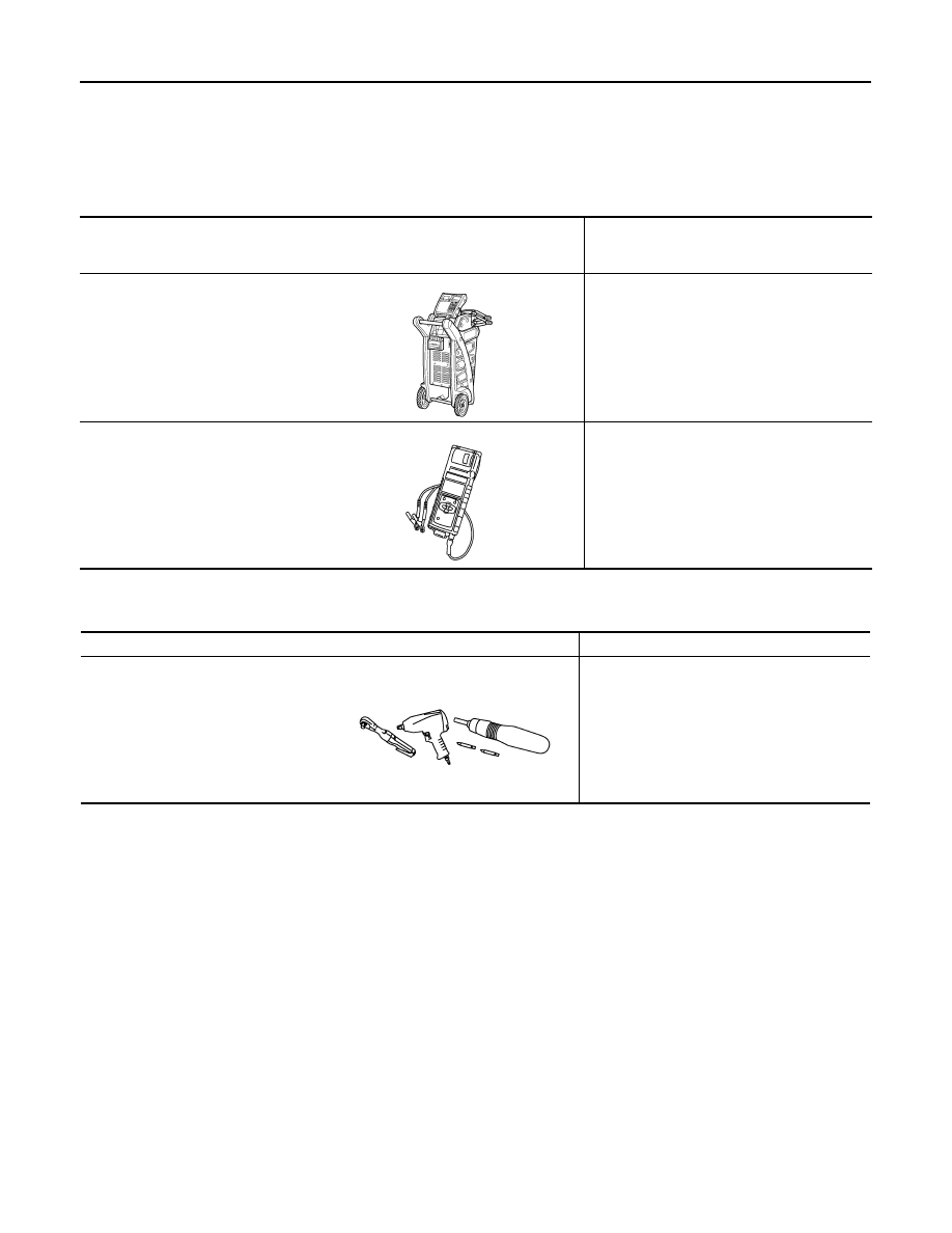
Commercial Service Tool

INFOID:0000000009755952

Tool number
(TechMate No.)
Tool name

Description

(—) Model GR8-1200 NI 
Multitasking battery and electrical di-
agnostic station

Tests batteries, starting and charging sys-
tems and charges batteries.
For operating instructions, refer to diagnostic 
station instruction manual.

(—) Model EXP-800 NI
Battery and electrical diagnostic ana-
lyzer

Tests batteries and charging systems.
For operating instructions, refer to diagnostic 
analyzer instruction manual.

AWIIA1239ZZ

JSMIA0806ZZ

Tool name

Description

Power tool

Loosening nuts, screws and bolts

PIIB1407E

CHG

COMPONENT PARTS

CHG-5

< SYSTEM DESCRIPTION >

C

D

E

F

G

H

I

J

K

L

B

A

O

P

N

SYSTEM DESCRIPTION

COMPONENT PARTS

Component Parts Location

INFOID:0000000009755953

AWMIA1322GB

1.

Generator

2.

IPDM E/R (view with air inlet duct re-
moved)

3.

ECM

4. 

Battery current sensor

5.

Charge warning lamp indicator

CHG-6

< SYSTEM DESCRIPTION >

COMPONENT PARTS

Component Description

INFOID:0000000009755954

Component part

Description

Generator (IC regulator)

The IC regulator controls the power generation voltage by the tar-
get power generation voltage based on the received PWM com-
mand signal.
When there is no PWM command signal, the generator performs 
the normal power generation according to the characteristic of the 
IC regulator.

IPDM E/R

The IPDM E/R converts the received power generation command 
value into a pulse width modulated (PWM) command signal and 
sends it to the IC regulator.

ECM

The battery current sensor detects the charging/discharging cur-
rent of the battery. The ECM judges the battery condition based on 
this signal.
The ECM judges whether to request more output via the power 
generation voltage variable control according to the battery condi-
tion.
When performing the power generation voltage variable control, 
the ECM calculates the target power generation voltage according 
to the battery condition and sends the calculated value as the pow-
er generation command value to the IPDM E/R.

Battery current sensor

The battery current sensor is located on the negative battery cable 
terminal. The battery current sensor detects the charging/dis-
charging current of the battery and sends a voltage signal to the 
ECM according to the current value detected.

Combination meter (charge warning lamp) 

The IC regulator warning function activates to illuminate the 
charge warning lamp if any of the following symptoms occur while 
generator is operating:
·Excessive voltage is produced.
·No voltage is produced. 

CHG

CHARGING SYSTEM

CHG-7

< SYSTEM DESCRIPTION >

C

D

E

F

G

H

I

J

K

L

B

A

O

P

N

CHARGING SYSTEM

System Diagram

INFOID:0000000009755955

System Description

INFOID:0000000009755956

The generator provides DC voltage to operate the vehicle's electrical system and to keep the battery charged.

The voltage output is controlled by the IC regulator.

Component Description

INFOID:0000000009755957

AWMIA1334GB

Component part

Description

Generator

Terminal “1” 

Refer to 

CHG-23, "Description"

.

Terminal “2”

Refer to 

CHG-24, "Description"

.

Terminal “3”

Refer to 

CHG-27, "Description"

.

Terminal “4” 

Used for the power generation voltage variable control system. 
Refer to 

CHG-8, "System Description"

.

Combination meter (Charge warning lamp)

The IC regulator warning function activates to illuminate the 
charge warning lamp if any of the following symptoms occur while 
generator is operating:
• Excessive voltage is produced.
• No voltage is produced.

IPDM E/R

Used for the power generation voltage variable control system. 
Refer to 

CHG-8, "System Description"

.


Content   ..  195  196  197  198   ..