Nissan Sentra. Manual - part 176
PARKING BRAKE SWITCH
BRC-91
< DTC/CIRCUIT DIAGNOSIS >
[VDC/TCS/ABS]
C
D
E
G
H
I
J
K
L
M
A
B
BRC
N
O
P
Is the inspection result normal?
YES
>> Replace combination meter. Refer to
MWI-77, "Removal and Installation"
NO
>> Repair or replace malfunctioning components.
Component Inspection
INFOID:0000000009757878
1.
CHECK PARKING BRAKE SWITCH
1. Turn ignition switch OFF.
2. Disconnect parking brake switch connector.
3. Check continuity between parking brake switch terminal 1 and ground.
Is the inspection result normal?
YES
>> Inspection End.
NO
>> Replace parking brake switch. Refer to
.
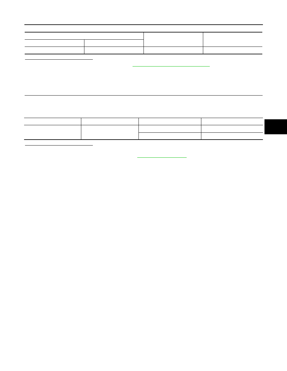
Combination meter
—
Continuity
Connector
Terminal
M24
10
Ground
No
Parking brake switch terminal
—
Condition
Continuity
1
Ground
Parking brake actuated
Yes
Parking brake released
No