Nissan Sentra. Manual - part 155
COMPONENT PARTS
BRC-7
< SYSTEM DESCRIPTION >
[VDC/TCS/ABS]
C
D
E
G
H
I
J
K
L
M
A
B
BRC
N
O
P
SYSTEM DESCRIPTION
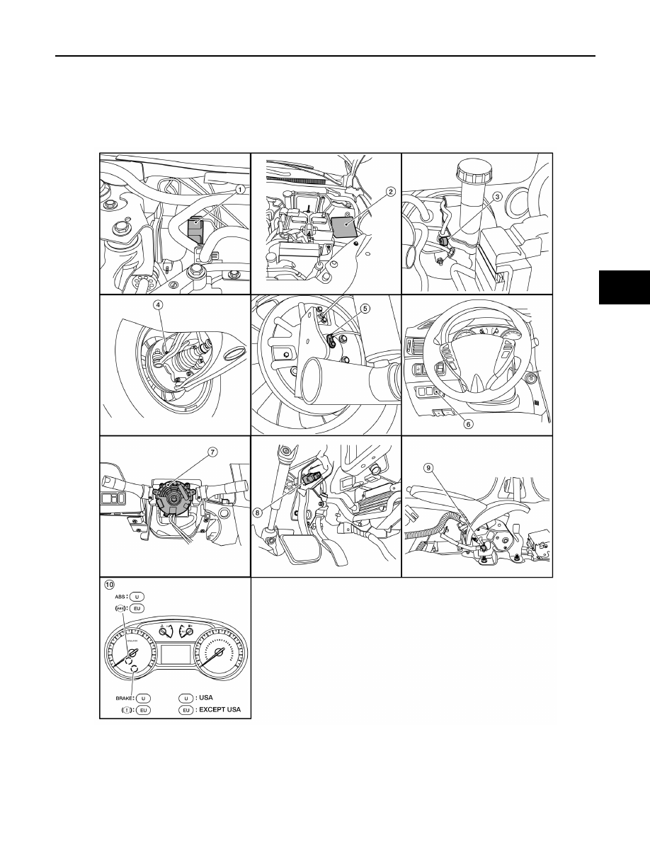
COMPONENT PARTS
Component Parts Location
INFOID:0000000009757807
1.
ABS actuator and electric unit (con-
trol unit)
2.
IPDM E/R
3.
Brake fluid level switch
4.
Front wheel sensor LH (RH similar)
5.
Rear wheel sensor LH (RH similar)
6.
VDC OFF switch
ALFIA0342ZZ