Nissan Sentra. Manual - part 118
BCS-42
< ECU DIAGNOSIS INFORMATION >
[WITH INTELLIGENT KEY SYSTEM]
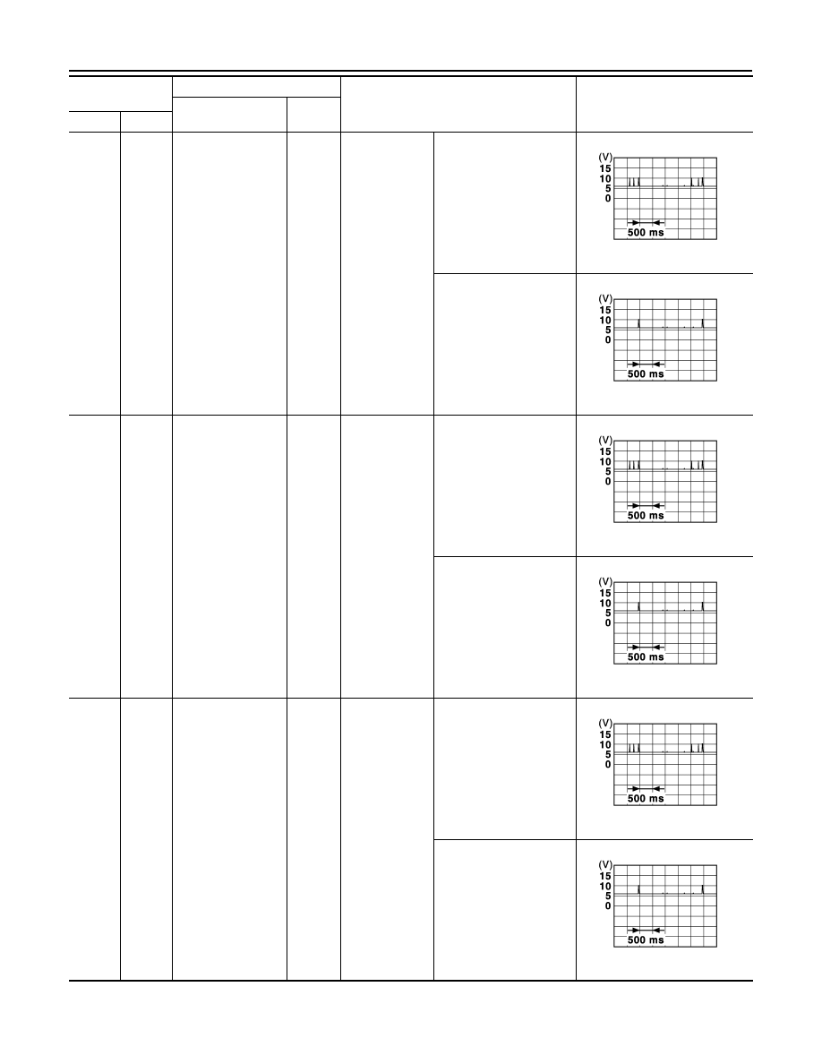
BCM
50
(Y)
Ground Door antenna (AS) -
Output
Push-button ig-
nition switch ON
Passenger door
request switch
pressed
Intelligent Key not in an-
tenna detection area
(Approx. 2 m)
Intelligent Key in antenna
detection area
(80 cm or less)
51
(BR)
Ground Door antenna (AS) +
Output
Push-button ig-
nition switch ON
Passenger door
request switch
pressed
Intelligent Key not in an-
tenna detection area
(Approx. 2 m)
Intelligent Key in antenna
detection area
(80 cm or less)
52
(LG)
Ground Door antenna (DR) -
Output
Push-button ig-
nition switch ON
Driver door re-
quest switch
pressed
Intelligent Key not in an-
tenna detection area
(Approx. 2 m)
Intelligent Key in antenna
detection area
(80 cm or less)
Terminal No.
(Wire color)
Description
Condition
Value
(Approx.)
Signal name
Input/
Output
+
−
JMKIA5954GB
JMKIA5955GB
JMKIA5954GB
JMKIA5955GB
JMKIA5954GB
JMKIA5955GB