Nissan Sentra. Manual - part 110


  Index      Nissan     Nissan Sentra (2014 year) - Service and Repair Manual


Search            


Content   ..  108  109  110  111   ..


Nissan Sentra. Manual - part 110


BCS-10

< SYSTEM DESCRIPTION >

[WITH INTELLIGENT KEY SYSTEM]

SYSTEM

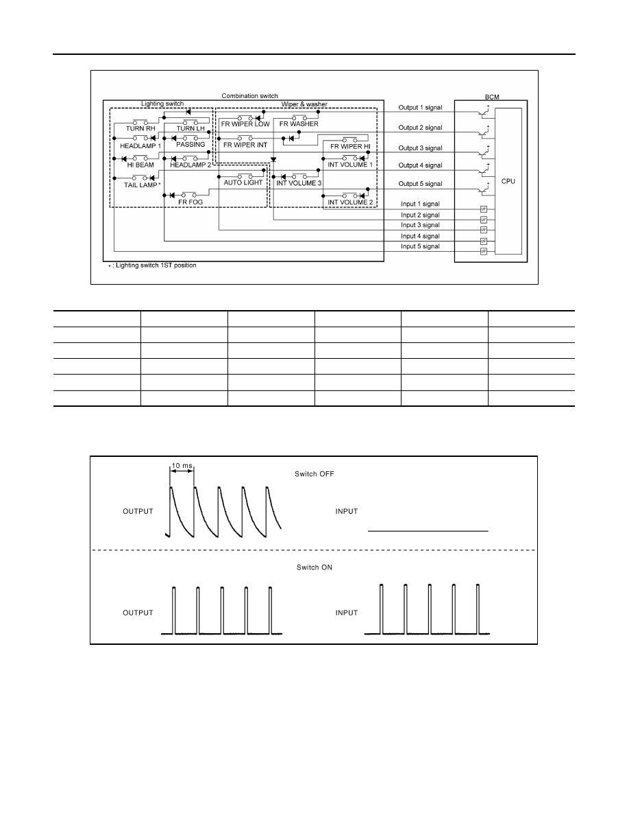
Combination switch circuit

Combination switch INPUT-OUTPUT system list

COMBINATION SWITCH READING FUNCTION

Description

• BCM reads the status of the combination switch at 10 ms intervals normally.

NOTE:

BCM reads the status of the combination switch at 60 ms intervals when BCM is controlled at low power

consumption control mode.

• BCM operates as follows and judges the status of the combination switch.

- It operates the transistor on OUTPUT side in the following order: OUTPUT 1 

→ 2 → 3 → 4 → 5, and outputs

voltage waveform.

- The voltage waveform of OUTPUT corresponding to the formed circuit is input into the interface on INPUT

side if any (1 or more) switches are ON.

System

INPUT 1

INPUT 2

INPUT 3

INPUT 4

INPUT 5

OUTPUT 1

FR WASHER

FR WIPER LOW

TURN LH

TURN RH

OUTPUT 2

FR WIPER HI

FR WIPER INT

PASSING

HEADLAMP 1

OUTPUT 3

INT VOLUME 1

HEADLAMP 2

HI BEAM

OUTPUT 4

INT VOLUME 3

AUTO LIGHT

TAIL LAMP

OUTPUT 5

INT VOLUME 2

FR FOG

AWMIA1360GB

JPMIA0609GB

BCS

SYSTEM

BCS-11

< SYSTEM DESCRIPTION >

[WITH INTELLIGENT KEY SYSTEM]

C

D

E

F

G

H

I

J

K

L

B

A

O

P

N

- It reads this change of the voltage as the status signal of the combination switch.

Operation Example

In the following operation example, the combination of the status signals of the combination switch is replaced

as follows: INPUT 1 - 5 to “1 - 5” and OUTPUT 1 - 5 to “A - E”.

Example 1: When a switch (TAIL LAMP) is turned ON

• The circuit between OUTPUT 4 and INPUT 5 is formed when the TAIL LAMP switch is turned ON.

• BCM detects the combination switch status signal “5D” when the signal of OUTPUT 4 is input to INPUT 5.

• BCM judges that the TAIL LAMP switch is ON when the signal “5D” is detected.

Example 2: When some switches (TURN RH, TAIL LAMP) are turned ON

JMMIA0326GB

AWMIA1361GB

BCS-12

< SYSTEM DESCRIPTION >

[WITH INTELLIGENT KEY SYSTEM]

SYSTEM

• The circuits between OUTPUT 1 and INPUT 5 and between OUTPUT 4 and INPUT 5 are formed when the

TURN RH switch and TAIL LAMP switch are turned ON.

• BCM detects the combination switch status signal “5AD” when the signals of OUTPUT 1 and OUTPUT 4 are

input to INPUT 5.

• BCM judges that the TURN RH switch and TAIL LAMP switch are ON when the signal “5AD” is detected.

WIPER INTERMITTENT DIAL POSITION

BCM judges the wiper intermittent dial 1 - 7 by the status of INT VOLUME 1, 2 and 3 switches.

NOTE:
For details of wiper intermittent dial position, refer to 

WW-8, "System Description"

.

SIGNAL BUFFER SYSTEM
SIGNAL BUFFER SYSTEM : System Diagram

INFOID:0000000009757302

AWMIA1362GB

Wiper intermittent

dial position

Switch status

INT VOLUME 1

INT VOLUME 2

INT VOLUME 3

1

ON

ON

ON

2

ON

ON

OFF

3

ON

OFF

OFF

4

OFF

OFF

OFF

5

OFF

OFF

ON

6

OFF

ON

ON

7

OFF

ON

OFF

AWMIA1275GB

BCS

SYSTEM

BCS-13

< SYSTEM DESCRIPTION >

[WITH INTELLIGENT KEY SYSTEM]

C

D

E

F

G

H

I

J

K

L

B

A

O

P

N

SIGNAL BUFFER SYSTEM : System Description

INFOID:0000000009757303

OUTLINE

BCM has the signal transmission function that outputs/transmits each input/received signal to each unit.

Signal transmission function list

POWER CONSUMPTION CONTROL SYSTEM
POWER CONSUMPTION CONTROL SYSTEM : System Diagram

INFOID:0000000009757304

POWER CONSUMPTION CONTROL SYSTEM : System Description

INFOID:0000000009757305

OUTLINE

• BCM incorporates a power saving control function that reduces the power consumption according to the

vehicle status. 

• BCM switches the status (control mode) by itself with the power saving control function. It performs the sleep

request to each unit (IPDM E/R and combination meter) that operates with the ignition switch OFF.

Normal mode (wake-up)

- CAN communication is normally performed with other units

- Each control with BCM is operating properly

CAN communication sleep mode (CAN sleep)

- CAN transmission is stopped

- Control with BCM only is operating

Low power consumption mode (BCM sleep)

- Low power consumption control is active

- CAN transmission is stopped

LOW POWER CONSUMPTION CONTROL WITH BCM

BCM reduces the power consumption with the following operation in the low power consumption mode.

• The reading interval of each switch changes from 10 ms interval to 60 ms interval.

Sleep mode activation

Signal name

Input

Output

Description

• Ignition switch ON signal
• Ignition switch signal

Engine switch (push switch)

IPDM E/R (CAN)

Inputs the push-button ignition 
switch (push switch) signal and 
transmits the ignition switch sta-
tus judged with BCM via CAN 
communication.

Door switch signal

Any door switch

• Combination meter (CAN)
• IPDM E/R (CAN)

Inputs the door switch signal 
and transmits it via CAN com-
munication.

ALCIA0030GB


Content   ..  108  109  110  111   ..