Nissan Sentra. Manual - part 81
AV-316
< SYSTEM DESCRIPTION >
[NAVIGATION WITH BOSE]
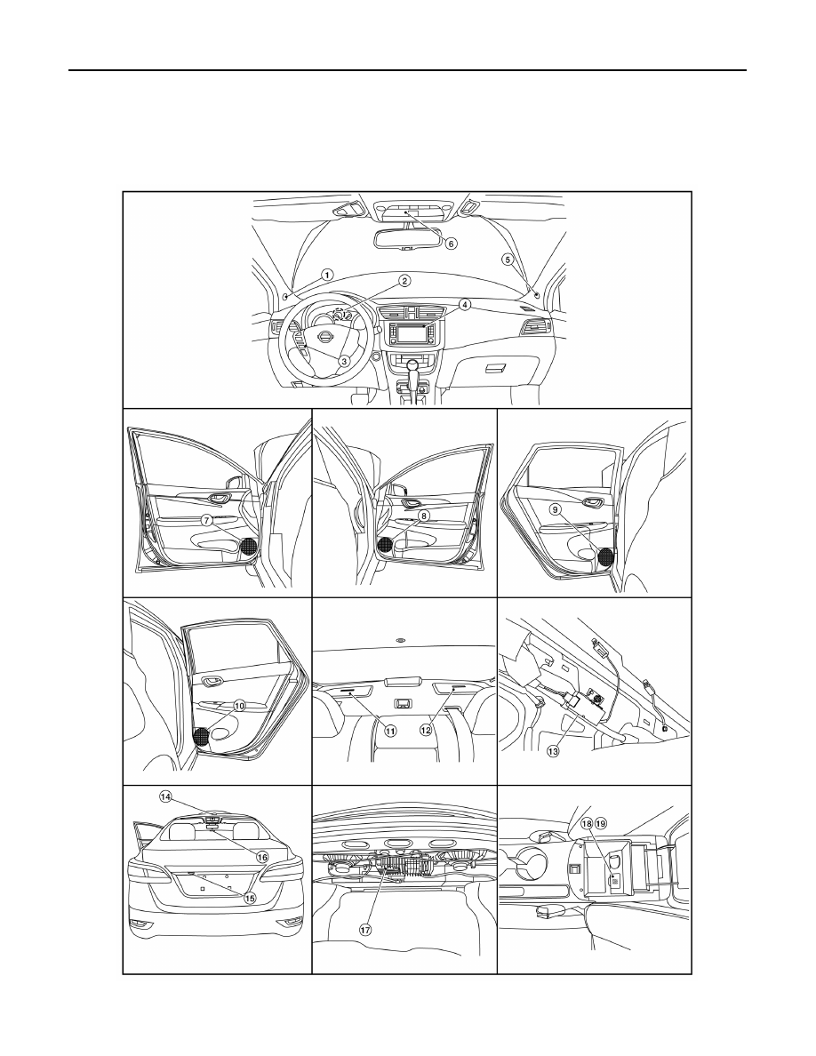
COMPONENT PARTS
SYSTEM DESCRIPTION
COMPONENT PARTS
Component Parts Location
INFOID:0000000009759006
ALNIA1459ZZ
|
|
|
AV-316 < SYSTEM DESCRIPTION > [NAVIGATION WITH BOSE] COMPONENT PARTS SYSTEM DESCRIPTION COMPONENT PARTS Component Parts Location INFOID:0000000009759006 ALNIA1459ZZ |