Nissan Sentra. Manual - part 56


  Index      Nissan     Nissan Sentra (2014 year) - Service and Repair Manual


Search            


Content   ..  54  55  56  57   ..


Nissan Sentra. Manual - part 56


AV-216

< REMOVAL AND INSTALLATION >

[DISPLAY AUDIO WITH BOSE]

SATELLITE RADIO ANTENNA

SATELLITE RADIO ANTENNA

Removal and Installation

INFOID:0000000009758924
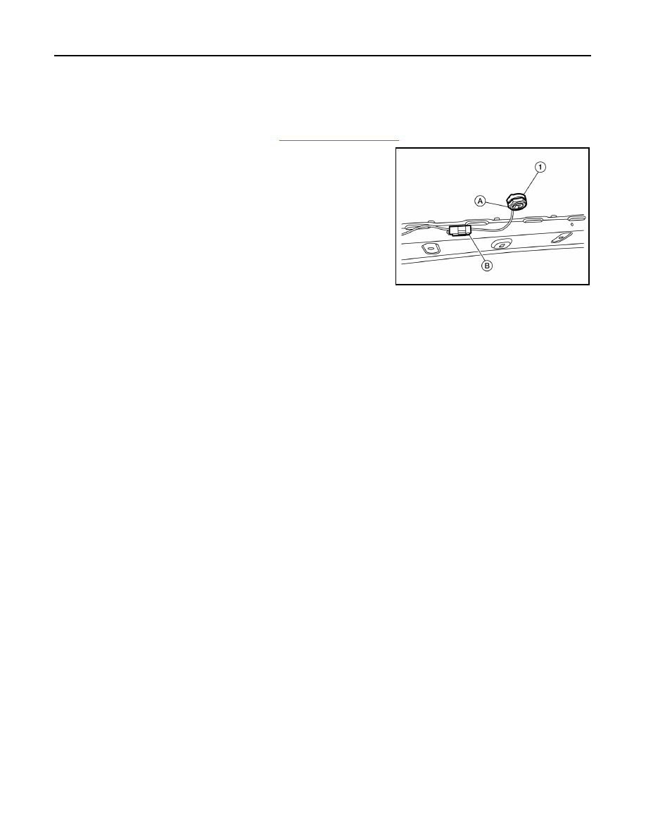
REMOVAL

1. Lower the headlining at the rear. Refer to 

INT-38, "Exploded View"

.

2. Remove the satellite radio antenna nut (A).
3. Disconnect the harness connector (B) from the satellite radio

antenna (1) and remove.

INSTALLATION

Installation is in the reverse order of removal.

ALNIA1412ZZ

AV

BLUETOOTH CONTROL UNIT

AV-217

< REMOVAL AND INSTALLATION >

[DISPLAY AUDIO WITH BOSE]

C

D

E

F

G

H

I

J

K

L

M

B

A

O

P

BLUETOOTH CONTROL UNIT

Removal and Installation

INFOID:0000000009758925

REMOVAL

1. Remove the glove box assembly. Refer to 

IP-22, "Removal and Installation"

.

2. Remove the Bluetooth control unit screws (A) and position aside

the Bluetooth control unit assembly (1). 

3. Disconnect the Bluetooth control unit connectors (C) and

release the harness retainer (B) from the Bluetooth control unit

bracket.

4. Release the harness clip (D) from the Bluetooth control unit

bracket and remove the Bluetooth control unit (1). 

5. Remove the Bluetooth control unit bracket screws (A), then

remove the Bluetooth control unit (2) from the Bluetooth control

unit bracket (1).

INSTALLATION

Installation is in the reverse order of removal.

ALNIA1417ZZ

ALNIA1418ZZ

AV-218

< REMOVAL AND INSTALLATION >

[DISPLAY AUDIO WITH BOSE]

MICROPHONE

MICROPHONE

Removal and Installation

INFOID:0000000009758926

REMOVAL 

1. Remove the front room/map lamp assembly. Refer to 

INL-52, "Removal and Installation"

.

2. Disconnect the microphone connector (A) from the front room/

map lamp assembly (2).

3. Release the microphone pawls, then remove the microphone

(1).

: Pawl

INSTALLATION

Installation is in the reverse order of removal.

ALNIA1366ZZ

AV

PRECAUTIONS

AV-219

< PRECAUTION >

[NAVIGATION WITHOUT BOSE]

C

D

E

F

G

H

I

J

K

L

M

B

A

O

P

PRECAUTION

PRECAUTIONS

Precaution for Supplemental Restraint System (SRS) "AIR BAG" and "SEAT BELT 
PRE-TENSIONER"

INFOID:0000000010296648

The Supplemental Restraint System such as “AIR BAG” and “SEAT BELT PRE-TENSIONER”, used along

with a front seat belt, helps to reduce the risk or severity of injury to the driver and front passenger for certain

types of collision. Information necessary to service the system safely is included in the SR and SB section of

this Service Manual.

WARNING:

• To avoid rendering the SRS inoperative, which could increase the risk of personal injury or death in

the event of a collision which would result in air bag inflation, all maintenance must be performed by

an authorized NISSAN/INFINITI dealer.

• Improper maintenance, including incorrect removal and installation of the SRS, can lead to personal

injury caused by unintentional activation of the system. For removal of Spiral Cable and Air Bag

Module, see the SR section.

• Do not use electrical test equipment on any circuit related to the SRS unless instructed to in this

Service Manual. SRS wiring harnesses can be identified by yellow and/or orange harnesses or har-

ness connectors.

PRECAUTIONS WHEN USING POWER TOOLS (AIR OR ELECTRIC) AND HAMMERS

WARNING:

• When working near the Airbag Diagnosis Sensor Unit or other Airbag System sensors with the Igni-

tion ON or engine running, DO NOT use air or electric power tools or strike near the sensor(s) with a

hammer. Heavy vibration could activate the sensor(s) and deploy the air bag(s), possibly causing

serious injury.

• When using air or electric power tools or hammers, always switch the Ignition OFF, disconnect the

battery and wait at least three minutes before performing any service.

Precaution for Trouble Diagnosis

INFOID:0000000009758928

AV COMMUNICATION SYSTEM

• Do not apply voltage of 7.0 V or higher to the measurement terminals.

• Use the tester with its open terminal voltage being 7.0 V or less.

• Be sure to turn ignition switch OFF and disconnect the battery cable from the negative terminal before

checking the circuit.

Precaution for Harness Repair

INFOID:0000000009758929

AV COMMUNICATION SYSTEM

• Solder the repaired parts, and wrap with tape. [Frays of twisted line

must be within 110 mm (4.33 in).]

PKIA0306E


Content   ..  54  55  56  57   ..