Nissan Sentra. Manual - part 47
AV-180
< DTC/CIRCUIT DIAGNOSIS >
[DISPLAY AUDIO WITH BOSE]
FRONT TWEETER
Is the inspection result normal?
YES
>> Replace front tweeter. Refer to
AV-204, "Removal and Installation"
NO
>> GO TO 4
4.
CHECK FRONT TWEETER SIGNAL CIRCUIT CONTINUITY (AUDIO UNIT)
1. Turn ignition switch to OFF.
2. Disconnect Bose speaker amp. connector B43 and audio unit connector M94.
3. Check continuity between Bose speaker amp. connector B43 and audio unit connector M94.
4. Check continuity between Bose speaker amp. connector B43 and ground.
Is the inspection result normal?
YES
>> GO TO 5
NO
>> Repair or replace harness or connectors.
5.
CHECK FRONT TWEETER SIGNAL (AUDIO UNIT)
1. Connect Bose speaker amp. connector B43 and audio unit connector M94.
2. Turn ignition switch to ACC.
3. Push audio unit POWER switch.
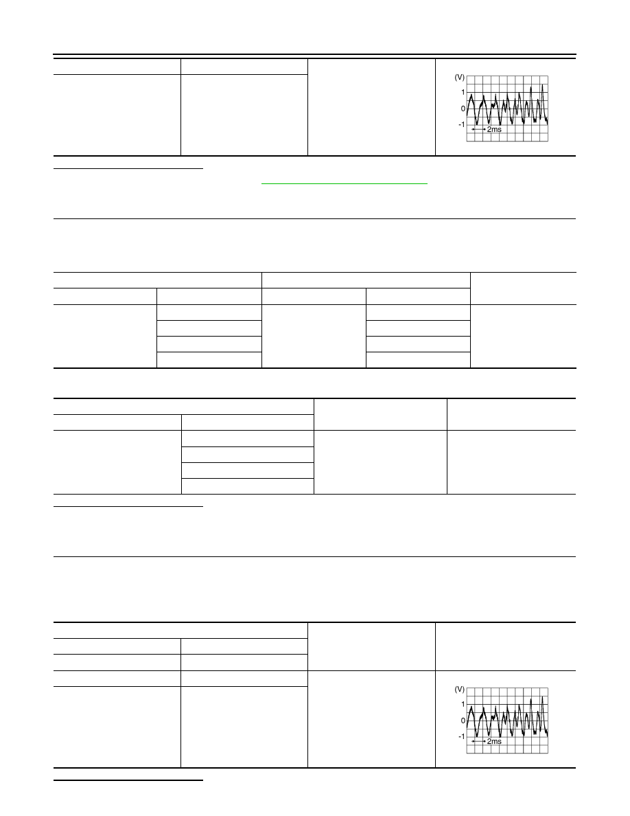
4. Check signal between the terminals of audio unit connector M94.
Is the inspection result normal?
37
36
Audio signal output
34
35
SKIB3609E
Bose speaker amp.
Audio unit
Continuity
Connector
Terminal
Connector
Terminal
B43
2
M94
3
Yes
3
2
4
12
5
11
Bose speaker amp.
Ground
Continuity
Connector
Terminal
B43
2
—
No
3
4
5
Audio unit connector M94
Condition
Reference value
(+)
(
−)
Terminal
Terminal
2
3
Audio signal output
11
12
SKIB3609E