Nissan Leaf. Manual - part 981


  Index      Nissan     Nissan Leaf (2011-2014 year) - Service and Repair Manual


Search            


Content   ..  979  980  981  982   ..


Nissan Leaf. Manual - part 981


PCS

SYSTEM

PCS-7

< SYSTEM DESCRIPTION >

[IPDM E/R]

C

D

E

F

G

H

I

J

K

L

B

A

O

P

N

SYSTEM

RELAY CONTROL SYSTEM
RELAY CONTROL SYSTEM : System Description

INFOID:0000000010120283
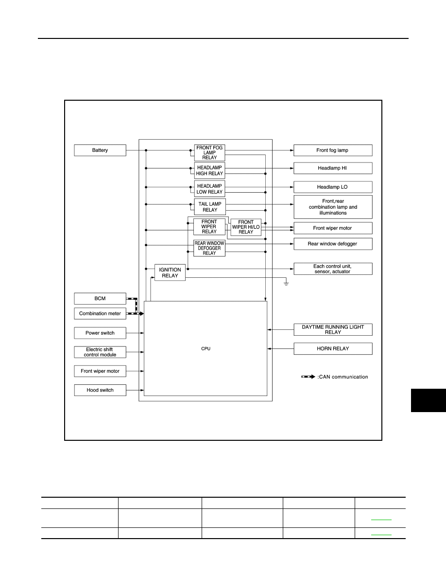
SYSTEM DIAGRAM

DESCRIPTION

IPDM E/R activates the internal control circuit to perform the relay ON-OFF control according to the input sig-

nals from various sensors and the request signals received from control units via CAN communication.

CAUTION:

To prevent damage to the parts, IPDM E/R integrated relays cannot be removed.

JMMIA0934GB

Control relay

Input/output

Transmit unit

Control part

Reference page

• Headlamp low relay
• Headlamp high relay

• Low beam request signal
• High beam request signal

BCM (CAN)

• Headlamp (LO)
• Headlamp (HI)

EXL-14

Front fog lamp relay

Front fog light request signal BCM (CAN)

Front fog lamp

EXL-21

PCS-8

< SYSTEM DESCRIPTION >

[IPDM E/R]

SYSTEM

*: For Canada

RELAY CONTROL SYSTEM : Fail-Safe

INFOID:0000000010563574

CAN COMMUNICATION CONTROL

When CAN communication with BCM is impossible, IPDM E/R performs fail-safe control. After CAN communi-

cation recovers normally, it also returns to normal control.

If No CAN Communication Is Available With BCM

IGNITION RELAY MALFUNCTION DETECTION FUNCTION

• IPDM E/R monitors the voltage at the contact circuit and excitation coil circuit of the ignition relay inside it. 

• IPDM E/R judges the ignition relay error if the voltage differs between the contact circuit and the excitation

coil circuit.

Tail lamp relay

Position light request signal

BCM (CAN)

• Parking  lamp
• License plate lamp
• Tail lamp
• Side marker lamp

EXL-20

Illumination

INL-8

• Front wiper relay
• Front wiper HI/LO relay

Front wiper request signal

BCM (CAN)

Front wiper motor

WW-8

Front wiper stop position 
signal

Front wiper motor

Rear window defogger re-
lay

Rear window defogger con-
trol signal

BCM (CAN)

Rear window defogger

DEF-7, "Sys-

tem Description"

Daytime running light re-
lay

*

Daytime running light re-
quest signal

BCM (CAN)

Daytime running light

EXL-18, "DAY-

TIME RUNNING 
LIGHT SYSTEM 

: System De-

scription"

Horn relay

Theft warning horn request 
signal

BCM (CAN)

Vehicle security horn

SEC-18

Ignition relay

Power switch ON signal

BCM (CAN)

Each control unit, sen-
sor, actuator and relay 
(Ignition power supply) 

PCS-26

Vehicle speed signal (Meter) Combination meter (CAN)

Power switch signal

Power switch

Control relay

Input/output

Transmit unit

Control part

Reference page

Control part

Fail-safe operation

Headlamp

• Turns ON the headlamp low relay when the power switch is turned ON
• Turns OFF the headlamp low relay when the power switch is turned OFF
• Headlamp high relay OFF

• Parking  lamp
• License plate lamp
• Illumination
• Tail lamp
• Side marker lamp

• Turns ON the tail lamp relay when the power switch is turned ON
• Turns OFF the tail lamp relay when the power switch is turned OFF

Front wiper motor

• The status just before activation of fail-safe control is maintained until the power switch is turned OFF 

while the front wiper is operating at LO or HI speed.

• The wiper is operated at LO speed until the power switch is turned OFF if the fail-safe control is activated 

while the front wiper is set in the INT mode and the front wiper motor is operating.

• Returns automatically wiper to stop position when power switch is turned ON if fail-safe control is acti-

vated while front wiper motor is operated and wiper stop in the other position than stop position.

• The status is held at service position if the fail-safe control is activated while the service position function 

is operating.

Front fog lamp

Front fog lamp relay OFF

Rear window defogger

Rear window defogger relay OFF

Horn

Horn relay OFF

Ignition relay

The status just before activation of fail-safe is maintained.

PCS

SYSTEM

PCS-9

< SYSTEM DESCRIPTION >

[IPDM E/R]

C

D

E

F

G

H

I

J

K

L

B

A

O

P

N

• If the ignition relay cannot turn OFF due to contact seizure, it activates the tail lamp relay for 10 minutes to

alert the user to the ignition relay malfunction when the power switch is turned OFF.

FRONT WIPER PROTECTION FUNCTION

IPDM E/R detects front wiper stop position by a front wiper stop position signal.

When a front wiper stop position signal is in the conditions listed below, IPDM E/R stops power supply to wiper

after repeating a front wiper 10 seconds activation and 20 seconds stop.

NOTE:

This operation status can be confirmed on the IPDM E/R “Data Monitor” that displays “BLOCK” for the item

“WIP PROT” while the wiper is stopped.

SIGNAL BUFFER SYSTEM
SIGNAL BUFFER SYSTEM : System Description

INFOID:0000000010120285

SYSTEM DIAGRAM

DESCRIPTION

• IPDM E/R receives the rear window defogger control signal from BCM via CAN communication and trans-

mits the rear window defogger status signal to VCM via CAN communication. Refer to 

DEF-7, "System

Description"

.

• IPDM E/R reads the hood switch and transmits the hood switch signal to BCM via CAN communication.

Refer to 

SEC-21, "VEHICLE SECURITY SYSTEM : System Description (For Canada)"

 (For Canada).

POWER CONSUMPTION CONTROL SYSTEM

Voltage judgment

IPDM E/R judgment

Operation

Ignition relay contact 

side

Ignition relay excitation 

coil side

ON

ON

Ignition relay ON normal

OFF

OFF

Ignition relay OFF normal

ON

OFF

Ignition relay ON stuck

• Detects DTC “B2098: IGN RELAY ON”
• Turns ON the tail lamp relay for 10 minutes

OFF

ON

Ignition relay OFF stuck

Detects DTC “B2099: IGN RELAY OFF”

Power switch

Front wiper switch

Front wiper stop position signal

ON

OFF

The front wiper stop position signal (stop position) cannot be input for 10 seconds.

ON

The front wiper stop position signal does not change for 10 seconds.

JMMIA0850GB

PCS-10

< SYSTEM DESCRIPTION >

[IPDM E/R]

SYSTEM

POWER CONSUMPTION CONTROL SYSTEM : System Description

INFOID:0000000010120286

SYSTEM DIAGRAM

DESCRIPTION

Outline

• IPDM E/R incorporates a power consumption control function that reduces the power consumption accord-

ing to the vehicle status. 

• IPDM E/R changes its status (control mode) with the sleep wake up signal received from BCM via CAN com-

munication.

Normal mode (wake-up)

- CAN communication is normally performed with other control units.

- Individual unit control by IPDM E/R is normally performed.

Low power consumption mode (sleep)

- Low power consumption control is active.

- CAN transmission is stopped.

Sleep Mode Activation

• IPDM E/R judges that the sleep-ready conditions are fulfilled when the power switch is OFF and none of the

conditions below are present. Then it transmits a sleep-ready signal (ready) to BCM via CAN communica-

tion.

- Outputting signals to actuators

- Switches or relays operating

- Output requests are being received from control units via CAN communication.

• IPDM E/R stops CAN communication and enters the low power consumption mode when it receives a sleep

wake up signal (sleep) from BCM and the sleep-ready conditions are fulfilled.

Wake-up Operation

• IPDM E/R changes from the low power consumption mode to the normal mode when it receives a sleep

wake up signal (wake up) from BCM or any of the following conditions is fulfilled. In addition, it transmits a

sleep-ready signal (not-ready) to BCM via CAN communication to report the CAN communication start.

- Power switch ON

- An output request is received from a control unit via CAN communication.

- Hood switch status changes. (For Canada)

JMMIA0613GB


Content   ..  979  980  981  982   ..