Nissan Leaf. Manual - part 913
LAN-114
< DTC/CIRCUIT DIAGNOSIS >
[CAN SYSTEM (TYPE 2)]
MAIN LINE BETWEEN IPDM-E AND DLC CIRCUIT
DTC/CIRCUIT DIAGNOSIS
MAIN LINE BETWEEN IPDM-E AND DLC CIRCUIT
Diagnosis Procedure
INFOID:0000000010415376
1.
CHECK CONNECTOR
1. Turn the power switch OFF.
2. Disconnect the 12V battery cable from the negative terminal. Refer to
LAN-26, "Precautions for Removing
3. Check the following terminals and connectors for damage, bend and loose connection (connector side
and harness side).
-
Harness connector E107
-
Harness connector B7
-
Harness connector B3
-
Harness connector M21
Is the inspection result normal?
YES
>> GO TO 2.
NO
>> Repair the terminal and connector.
2.
CHECK HARNESS CONTINUITY (OPEN CIRCUIT)
1. Disconnect the following harness connectors.
-
IPDM E/R
-
Harness connectors E107 and B7
2. Check the continuity between the IPDM E/R harness connector and the harness connector.
Is the inspection result normal?
YES
>> GO TO 3.
NO
>> Repair the main line between the IPDM E/R and the harness connector E107.
3.
CHECK HARNESS CONTINUITY (OPEN CIRCUIT)
1. Disconnect the harness connectors B3 and M21.
2. Check the continuity between the harness connectors.
Is the inspection result normal?
YES
>> GO TO 4.
NO
>> Repair the main line between the harness connectors B7 and B3.
4.
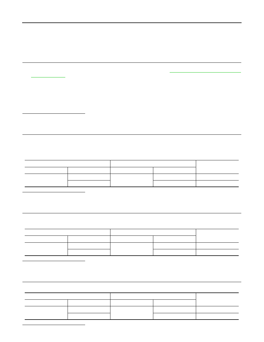
CHECK HARNESS CONTINUITY (OPEN CIRCUIT)
Check the continuity between the harness connector and the data link connector.
Is the inspection result normal?
IPDM E/R harness connector
Harness connector
Continuity
Connector No.
Terminal No.
Connector No.
Terminal No.
E13
27
E107
1
Existed
26
2
Existed
Harness connector
Harness connector
Continuity
Connector No.
Terminal No.
Connector No.
Terminal No.
B7
1
B3
31
Existed
2
32
Existed
Harness connector
Data link connector
Continuity
Connector No.
Terminal No.
Connector No.
Terminal No.
M21
31
M4
6
Existed
32
14
Existed