Nissan Leaf. Manual - part 899
LAN-58
< DTC/CIRCUIT DIAGNOSIS >
[CAN]
MAIN LINE BETWEEN INV/MC AND DLC CIRCUIT
MAIN LINE BETWEEN INV/MC AND DLC CIRCUIT
Diagnosis Procedure
INFOID:0000000010120380
1.
CHECK CONNECTOR
1. Turn the power switch OFF.
2. Disconnect the 12V battery cable from the negative terminal. Refer to
LAN-26, "Precautions for Removing
3. Check the following terminals and connectors for damage, bend and loose connection (connector side
and harness side).
-
Harness connector F2
-
Harness connector E60
-
Harness connector E105
-
Harness connector M77
Is the inspection result normal?
YES
>> GO TO 2.
NO
>> Repair the terminal and connector.
2.
CHECK HARNESS CONTINUITY (OPEN CIRCUIT)
1. Disconnect the following harness connectors.
-
Traction motor inverter
-
Harness connectors F2 and E60
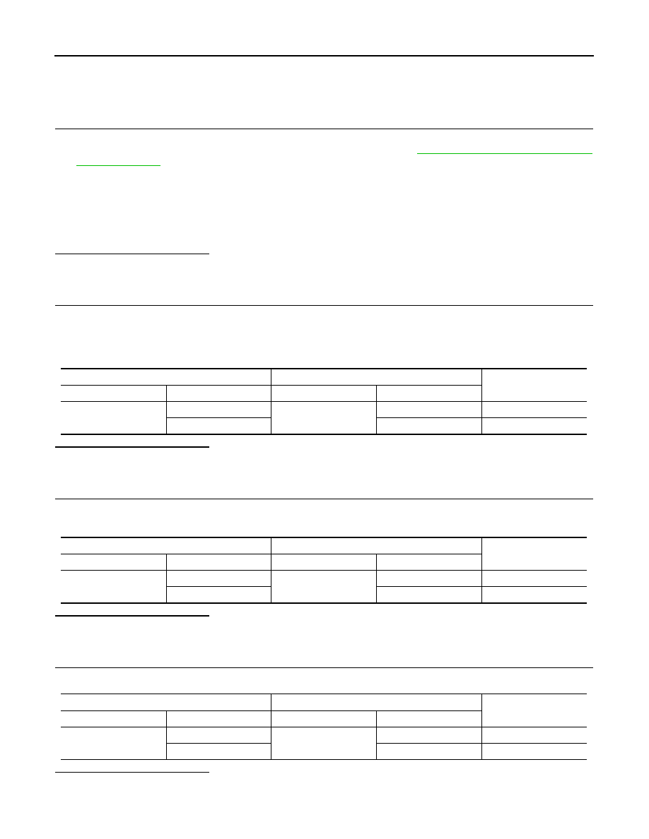
2. Check the continuity between the traction motor inverter harness connector and the harness connector.
Is the inspection result normal?
YES
>> GO TO 3.
NO
>> Repair the main line between the traction motor inverter and the harness connector F2.
3.
CHECK HARNESS CONTINUITY (OPEN CIRCUIT)
1. Disconnect the harness connectors E105 and M77.
2. Check the continuity between the harness connectors.
Is the inspection result normal?
YES
>> GO TO 4.
NO
>> Repair the main line between the harness connector E60 and the harness connector E105.
4.
CHECK HARNESS CONTINUITY (OPEN CIRCUIT)
Check the continuity between the harness connector and the data link connector.
Is the inspection result normal?
YES (Present error)>>Check CAN system type decision again.
Traction motor inverter harness connector
Harness connector
Continuity
Connector No.
Terminal No.
Connector No.
Terminal No.
F13
14
F2
5
Existed
15
6
Existed
Harness connector
Harness connector
Continuity
Connector No.
Terminal No.
Connector No.
Terminal No.
E60
5
E105
50
Existed
6
49
Existed
Harness connector
Data link connector
Continuity
Connector No.
Terminal No.
Connector No.
Terminal No.
M77
50
M4
13
Existed
49
12
Existed