Nissan Leaf. Manual - part 818
SYSTEM SETTING
HAC-275
< BASIC INSPECTION >
[AUTO A/C (WITHOUT HEAT PUMP)]
C
D
E
F
G
H
J
K
L
M
A
B
HAC
N
O
P
When the 12V battery cable is disconnected from the negative terminal or when the 12V battery voltage
becomes 10 V or less, the setting of the REC memory function may be cancelled.
Inlet Port Memory Function (FRE)
INFOID:0000000010121972
DESCRIPTION
• If the ignition switch is turned to the OFF position while the intake switch is set to OFF (fresh air intake), “Per-
form the memory” or “Do not perform the memory” of intake switch OFF (fresh air intake) condition can be
selected.
• If “Perform the memory” is set, the intake switch is OFF (fresh air intake) when turning the ignition switch to
the ON position again.
• If “Do not perform the memory” is set, the air inlets is controlled automatically when turning the ignition
switch to the ON position again.
HOW TO SET
With CONSULT
Perform the “FRE MEMORY SET” in “Work support” of “HVAC”.
NOTE:
When the 12V battery cable is disconnected from the negative terminal or when the 12V battery voltage
becomes 10 V or less, the setting of the FRE memory function may be cancelled.
Foot Position Setting Trimmer
INFOID:0000000010121973
DESCRIPTION
In FOOT mode, the air blowing to DEF can change ON/OFF.
HOW TO SET
With CONSULT
Perform the “BLOW SET” in “Work support” of “HVAC”.
NOTE:
When the 12V battery cable is disconnected from the negative terminal or when the 12V battery voltage
becomes 10 V or less, the setting of the discharge air mix ratio in FOOT mode may be cancelled.
Compressor Operation Setting at Defroster Mode (Timer/Remote Climate Control)
INFOID:0000000010121974
DESCRIPTION
For A/C-heater timer and remote climate control, change the setting of electric compressor operation during
DEF mode.
How to set
Using CONSULT, select “COMP OPRT SET AT DEF MODE (TIM/RMT CLIMT CONT)” in “Work support“ of
“HVAC”.
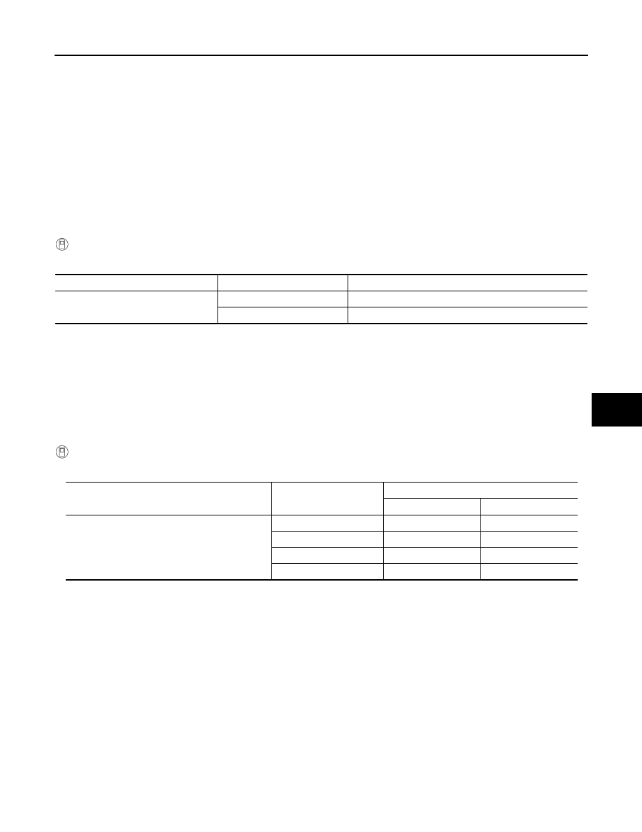
Work support items
Display
Setting
FRE MEMORY SET
WITHOUT
Perform the memory of manual FRE
WITH (initial status)
Do not perform the memory of manual FRE (auto control)
Work support items
Display
Defroster door position
Audio control
Manual control
BLOW SET
Mode1 (initial status)
OPEN
CLOSE
Mode2
OPEN
OPEN
Mode3
CLOSE
OPEN
Mode4
CLOSE
CLOSE