Nissan Leaf. Manual - part 811
A/C AUTO AMP.
HAC-247
< ECU DIAGNOSIS INFORMATION >
[AUTO A/C (WITHOUT HEAT PUMP)]
C
D
E
F
G
H
J
K
L
M
A
B
HAC
N
O
P
2
(R)
10
(B)
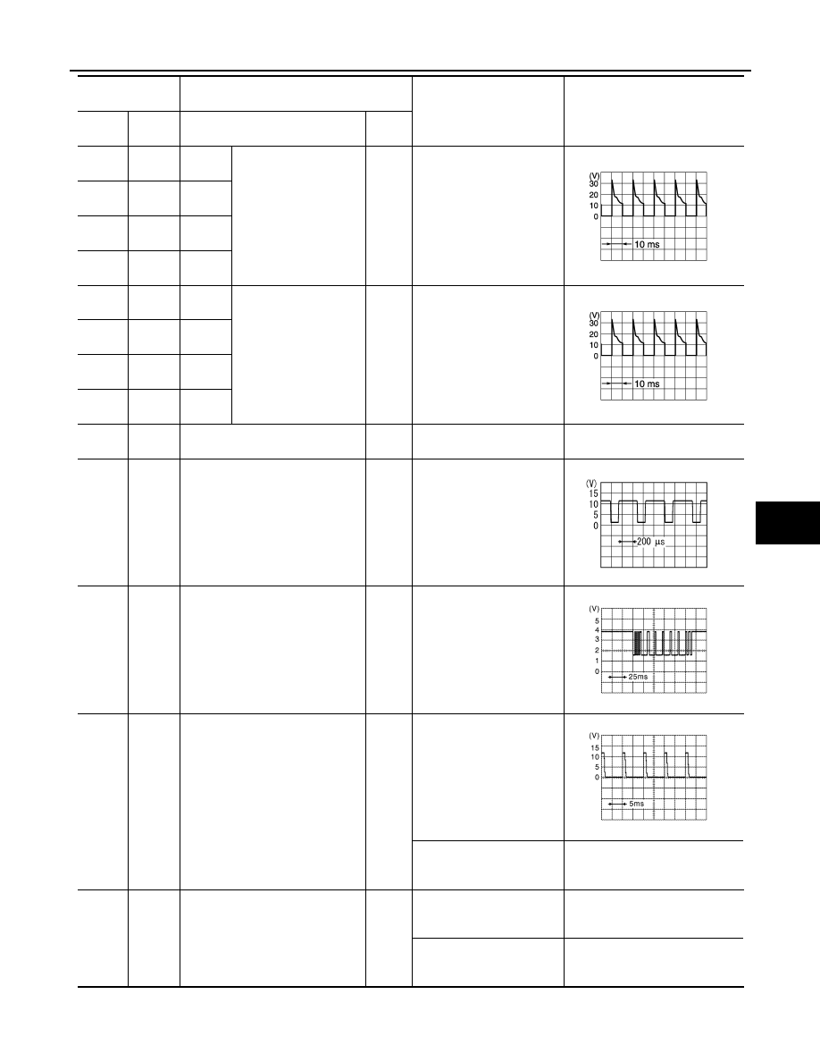
MODE
drive 4
Mode door motor drive
signal
Output
• Power switch ON
• Immediately after mode
switch is operated
3
(P)
10
(B)
MODE
drive 3
4
(BG)
10
(B)
MODE
drive 2
5
(V)
10
(B)
MODE
drive 1
6
(BR)
10
(B)
A/MIX
drive 4
Air mix door motor drive
signal
Output
• Power switch ON
• Immediately after temper-
ature control switch is op-
erated
7
(GR)
10
(B)
A/MIX
drive 3
8
(LG)
10
(B)
A/MIX
drive 2
9
(L)
10
(B)
A/MIX
drive 1
10
(B)
Ground
Ground
—
Power switch ON
0 – 0.1 V
12
(GR)
10
(B)
Power transistor control signal
Output
• Power switch ON
• Fan speed: Manual speed
1
14
(L)
10
(B)
COMP_TX
Output
• Power switch ON
• FULL COLD
• Electric compressor oper-
ation
15
(W)
10
(B)
Rear defogger switch
Output
• Power switch ON
• Rear window defogger
switch OFF
• Power switch ON
• Rear defogger switch is
pressed.
0 V
16
(LG)
10
(B)
Steering heater switch signal
Output
• Power switch ON
• Steering heater switch
OFF
0 V
• Power switch ON
• Steering heater switch is
pressed.
0.9 V or less
Terminal No.
(Wire color)
Item
Test condition
Standard
+
−
Signal name
Input/
Output
JPIIA1647GB
JPIIA1647GB
ZJIA0863J
JSIIA1658ZZ
JSIIA1668ZZ