Nissan Leaf. Manual - part 739


  Index      Nissan     Nissan Leaf (2011-2014 year) - Service and Repair Manual


Search            


Content   ..  737  738  739  740   ..


Nissan Leaf. Manual - part 739


HA-78

< SYSTEM DESCRIPTION >

[WITHOUT HEAT PUMP SYSTEM]

COMPONENT PARTS

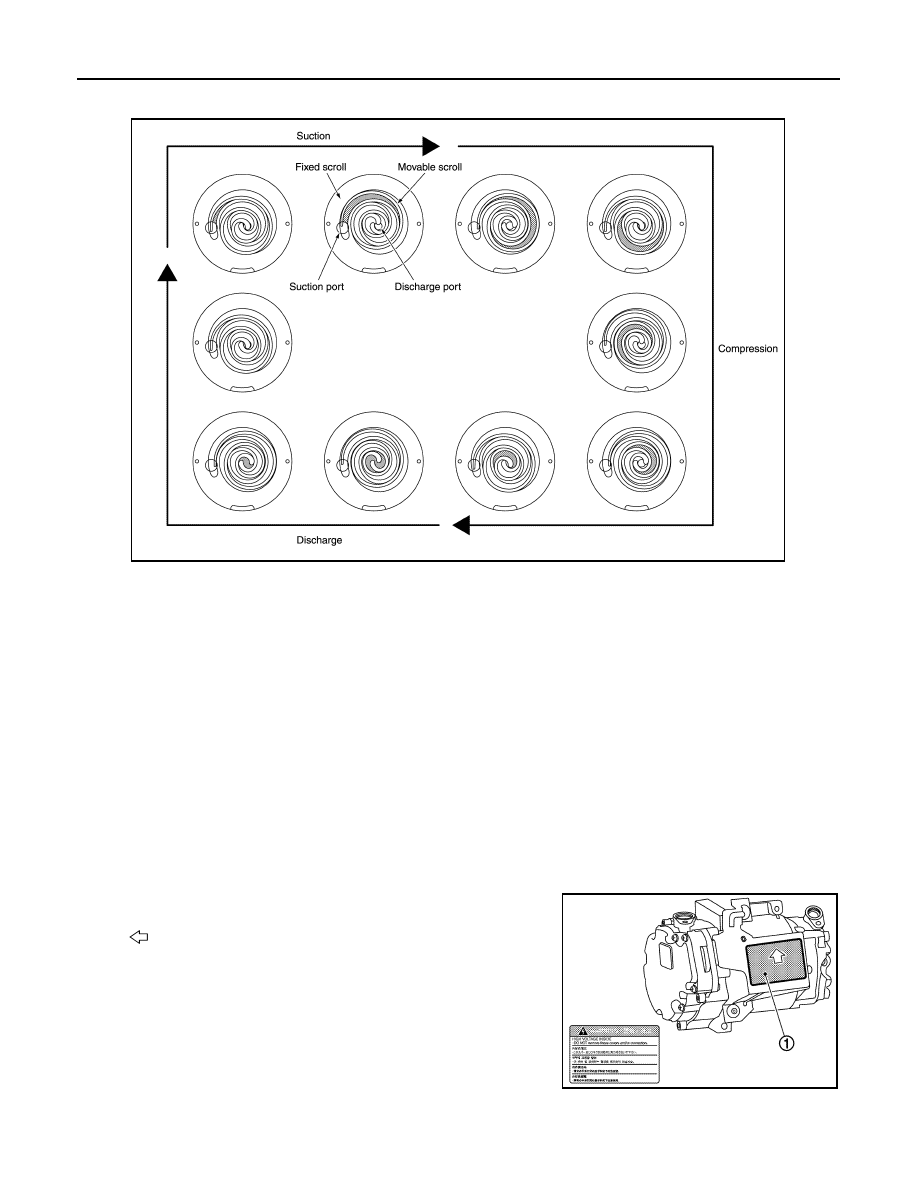
• A scroll-type compressor is used. The motor drive force is used to rotate the moveable scroll and perform

refrigerant intake, compression, and discharge.

Refrigerant and Compressor Oil

INFOID:0000000010122151

• The refrigerant is HFC-134a, which contains no chlorine (Cl), a substance which damages the ozone layer.

• The compressor oil is ND-OIL 11, an ester oil with high insulation performance, designed especially for elec-

tric compressors.

CAUTION:

• The special electric compressor oil has different properties from the conventional HFC-134a com-

pressor oil (PAG oil) and CFC-12 compressor oil (mineral oil). Be sure not to mix these oil types with

the compressor oil, as doing so may cause electric leakage.

NOTE:

• HFC: HydroFluoroCarbon

• CFC: ChloroFluoroCarbon

High Voltage Warning Label

INFOID:0000000010122152

• High voltage warning label is stuck on each component parts below.

• When replacing component parts make sure to stick it on original position.

Electric Compressor

The label (1) is stuck on the compressor stay.

PTC Heater

JSIIA1625GB

: Application direction of the label

JMIIA2629ZZ

COMPONENT PARTS

HA-79

< SYSTEM DESCRIPTION >

[WITHOUT HEAT PUMP SYSTEM]

C

D

E

F

G

H

J

K

L

M

A

B

HA

N

O

P

The label (1) is stuck on the housing of PTC heater.

JMIIA2585ZZ

HA-80

< SYSTEM DESCRIPTION >

[WITHOUT HEAT PUMP SYSTEM]

SYSTEM

SYSTEM

REFRIGERATION SYSTEM
REFRIGERATION SYSTEM : System Diagram

INFOID:0000000010122153

REFRIGERATION SYSTEM : System Description

INFOID:0000000010122154

REFRIGERANT CYCLE

Refrigerant Flow

The basic path of refrigerant flow is through the electric compressor, condenser, liquid tank, and evaporator,

and then it returns to the electric compressor. The vaporization of evaporator refrigerant is controlled by the

expansion valve.

Evaporator Cryoprotective Protection Control

• If the air temperature after passing through the evaporator (detected by the intake sensor) is 1

°C (34°F) or

less, the A/C auto amp., sends a request for speed 0 rpm to the electric compressor.

• Based on this signal from A/C auto amp., the electric compressor stops.

REFRIGERANT SYSTEM PROTECTION

Refrigerant Pressure Sensor

• The refrigerant system is protected from significant high pressure and low pressure by the refrigerant pres-

sure sensor that is installed on the liquid tank.

• The refrigerant pressure sensor outputs a signal to the VCM.

• If the A/C auto amp., judges that there is a malfunction (the conditions shown below) in the cooler cycle

based on the refrigerant pressure sensor detection value sent from VCM via EV CAN communications, it

stops operation of the electric compressor.

- Approximately 2,650 kPa (26.5 bar, 27.0 kg/cm

2

, 384.3 psi) or more

- Approximately 140 kPa (1.4 bar, 1.4 kg/cm

2

, 20.3 psi) or less

NOTE:

The values indicate gauge pressure.

Pressure Relief Valve

JSIIA1637GB

SYSTEM

HA-81

< SYSTEM DESCRIPTION >

[WITHOUT HEAT PUMP SYSTEM]

C

D

E

F

G

H

J

K

L

M

A

B

HA

N

O

P

• The refrigerant system is protected from significant high pressure by the pressure relief valve that is installed

in the electric compressor.

• If the pressure in the cooler cycle is excessively increased [3,500 kPa (35 bar, 35.7 kg/cm

2

, 507.5 psi) -

4,140 kPa (41.4 bar, 42.2 kg/cm

2

, 600.3 psi) or more], the pressure relief valve opens, releasing refrigerant

into the atmosphere.


Content   ..  737  738  739  740   ..