Nissan Leaf. Manual - part 693


  Index      Nissan     Nissan Leaf (2011-2014 year) - Service and Repair Manual


Search            


Content   ..  691  692  693  694   ..


Nissan Leaf. Manual - part 693


FRONT STABILIZER

FSU-21

< REMOVAL AND INSTALLATION >

C

D

F

G

H

I

J

K

L

M

A

B

FSU

N

O

P

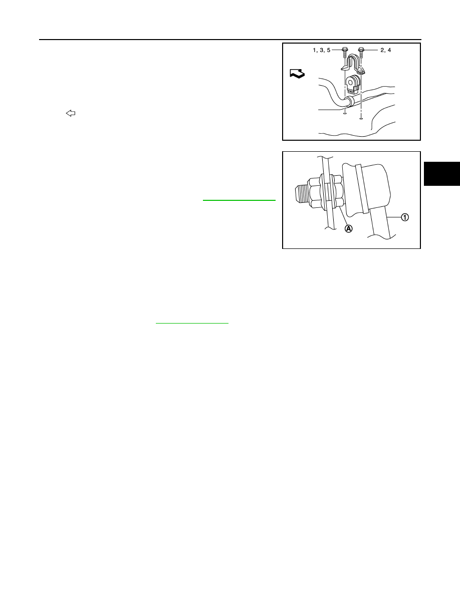
• To install stabilizer clamp bolt, follow the tightening method and the

numerical order shown below:

• To install stabilizer connecting rod (1), tighten the nut with the hex-

agonal part (A) on the stabilizer connecting rod side fixed.

• Perform final tightening of fixing parts at the vehicle installation

position (rubber bushing), under unladen conditions with tires on

level ground.

• Perform inspection after installation. Refer to 

FSU-17, "Inspection"

.

Inspection

INFOID:0000000010119440

INSPECTION AFTER REMOVAL

Check stabilizer bar, stabilizer connecting rod, stabilizer bushing and stabilizer clamp for deformation, cracks

or damage. Replace it if necessary.

INSPECTION AFTER INSTALLATION

Check wheel alignment. Refer to 

FSU-11, "Inspection"

.

Manual tightening

: 1

Temporary tightening

: 2 

→ 3

Final tightening (Specified torque) 

: 4 

→ 5

: Front

JPEIA0245GB

JPEIA0252ZZ

FSU-22

< REMOVAL AND INSTALLATION >

FRONT SUSPENSION MEMBER

FRONT SUSPENSION MEMBER

Exploded View

INFOID:0000000010119441

Removal and Installation

INFOID:0000000010119442

WARNING:

• Because hybrid vehicles and electric vehicles contain a high voltage battery, there is the risk of elec-

tric shock, electric leakage, or similar accidents if the high voltage component and vehicle are han-

dled incorrectly. Be sure to follow the correct work procedures when performing inspection and

maintenance.

• Be sure to remove the service plug in order to disconnect the high voltage circuits before perform-

ing inspection or maintenance of high voltage system harnesses and parts.

• To prevent the removed service plug from being connected by mistake during the procedure, always

carry it in your pocket or put it in the tool box.

• Be sure to wear insulating protective equipment consisting of glove, shoes, face shield and glasses

before beginning work on the high voltage system.

• Clearly identify the persons responsible for high voltage work and ensure that other persons do not

touch the vehicle. When not working, cover high voltage parts with an insulating cover sheet or sim-

ilar item to prevent other persons from contacting them. Refer to 

GI-33, "How to Disconnect High

Voltage"

.

CAUTION:

There is the possibility of a malfunction occurring if the vehicle is changed to READY status while the

service plug is removed. Therefore do not change the vehicle to READY status unless instructed to do

so in the Service Manual.

REMOVAL

WARNING:

Disconnect high voltage circuit. Refer to 

GI-33, "How to Disconnect High Voltage"

.

1. Check voltage in high voltage circuit. (Check that condenser are discharged.)
a. Lift up the vehicle and remove the Li-ion battery under covers. Refer to 

EVB-181, "Exploded View"

.

b. Disconnect high voltage harness connector from front side of Li-ion battery. Refer to 

GI-33, "How to Dis-

connect High Voltage"

.

1.

Front suspension member

2.

Rebound stopper rubber

3.

Insulator

4.

Member stay

5.

Rebound stopper

: N·m (kg-m, ft-lb)

JPEIA0275GB

FRONT SUSPENSION MEMBER

FSU-23

< REMOVAL AND INSTALLATION >

C

D

F

G

H

I

J

K

L

M

A

B

FSU

N

O

P

c. Measure voltage between high voltage harness terminals.

DANGER:


 Touching high voltage components without using the

appropriate protective equipment will cause electrocution.

CAUTION:

For voltage measurements, use a tester which can measure to 500 V or higher.

2. Remove 12V battery. Refer to 

FSU-5, "Precaution for Removing 12V Battery"

.

3. Remove front under cover. Refer to 

EXT-23, "FRONT UNDER COVER : Removal and Installation"

.

4. Remove traction motor inverter. Refer to 

TMS-103, "Removal and Installation"

.

5. Remove the bolts (A), then remove the compressor stay (1).

WARNING:

To prevent electric shock hazards, be sure to wear

protective gear.

6. Disconnect the high voltage harness connector (A) from electric

compressor.

WARNING:

To prevent electric shock hazards, be sure to wear

protective gear.

• Protect the terminals of disconnected high voltage har-

ness connector with insulation tape so that they are not

exposed.

• Follow the procedure below and disconnect the high voltage harness connector.

Standard

: 5 V or less 

JSAIA1362ZZ

JPIIA1763ZZ

JPIIA1764ZZ

JPCIA0037ZZ

FSU-24

< REMOVAL AND INSTALLATION >

FRONT SUSPENSION MEMBER

7. Disconnect the low voltage harness connector (A) from electric

compressor.

WARNING:

To prevent electric shock hazards, be sure to wear

protective gear.

8. Remove electric compressor (1). Hang electric compressor not

to interfere with work.

WARNING:

To prevent electric shock hazards, be sure to wear

protective gear.

CAUTION:

Do not apply excessive stress to high-pressure flexible

hose and low-pressure flexible hose.

9. Remove ground cable (1) from compressor bracket (2).

WARNING:

To prevent electric shock hazards, be sure to wear

protective gear.

10. Remove traction motor harness connector (1).

WARNING:

To prevent electric shock hazards, be sure to wear

protective gear.

JPIIA1765ZZ

: Front

JPEIA0278ZZ

: Front

JPEIA0279ZZ

2

: Water hose (lower side)

: Front

JPEIA0280ZZ


Content   ..  691  692  693  694   ..