Nissan Leaf. Manual - part 599


  Index      Nissan     Nissan Leaf (2011-2014 year) - Service and Repair Manual


Search            


Content   ..  597  598  599  600   ..


Nissan Leaf. Manual - part 599


EVC-420

< SYMPTOM DIAGNOSIS >

EV CONTROL SYSTEM

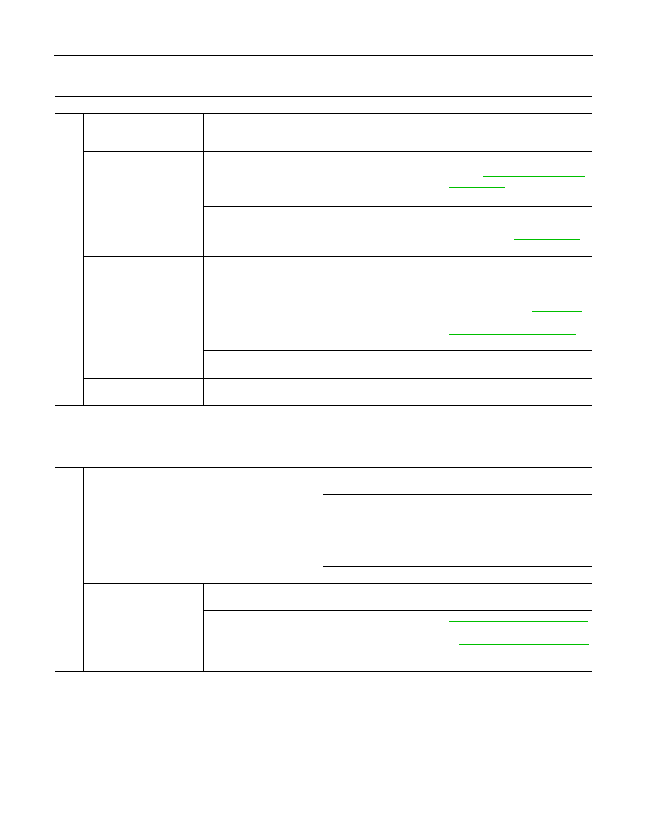
Full Charge Cannot Be Achieved

INFOID:0000000010120873

Climate Ctrl. Timer Does Not Start

INFOID:0000000010120874

Symptom

Possible cause

Action

Fu

ll ch

arg

e

 ca

nn

ot

 be

 ac

hi

ev

ed

.

Implementation of quick 
charge under a low Li-ion 
battery level.

Perform quick charge again.

Charge power is low or 
charging stops.

Power consumption is large 
during charge.

A/C power consumption is 
large.

Refer to 

EVC-412, "Low Electrical 

Consumption"

.

Power consumption of auxil-
iaries is large.

Charge power is limited.

Charge Insulation Resis-
tance Loss Protection Con-
trol is active.

Perform inspection according to the 
diagnosis procedure of DTC 
P3141. Refer to 

EVC-251, "DTC 

Logic"

.

Target charge level differs 
from the meter indication.

Indication decreases after 
the completion of charge.

Temperature change in Li-
ion battery.

Normal operation.
NOTE:
Charge level depends on Li-ion bat-
tery temperature. For meter indica-
tion method, refer to 

MWI-24, "LI-

ION BATTERY AVAILABLE 
CHARGE GAUGE : System De-
scription"

.

Meter indication does not 
reach maximum.

LED malfunction

MWI-48, "Description"

Charge level is low.

Chargeable electricity is lim-
ited.

LBC limits chargeable elec-
tricity.

Check “POWER LIMIT CAUSE” of 
DATA MONITOR item in VCM.

Symptom

Possible cause

Action

Clim

at

e Ct

rl. T

ime

r d

oes

 n

ot 

st

art.

Climate Ctrl. Timer start conditions are not satisfied.

Climate Ctrl. Timer is not 
set.

Set Climate Ctrl. Timer.

Remote climate control is 
set.

Normal operation.
NOTE:
If Climate Ctrl. Timer and remote 
climate control are requested simul-
taneously, remote climate control is 
prioritized.

EVSE is not connected.

Connect EVSE.

A/C system does not start.

A/C auto amp. does not rec-
ognize Climate Ctrl. Timer.

Abnormal A/C auto amp.

Perform self-diagnosis of A/C auto 
amp.

Abnormal A/C system pow-
er supply.

HAC-173, "A/C AUTO AMP. : Diag-
nosis Procedure"

 (with heat pump) 

or 

HAC-333, "A/C AUTO AMP. : Di-

agnosis Procedure"

 (without heat 

pump)

EV CONTROL SYSTEM

EVC-421

< SYMPTOM DIAGNOSIS >

D

E

F

G

H

I

J

K

L

M

A

B

EVC

N

O

P

Remote climate control Does Not Start

INFOID:0000000010120875

*: Only during no AC power input.

Symptom

Possible cause

Action

Re

m

ote

 c

lim

at

e c

on

trol

 d

oes

 n

ot

 st

art.

Remote climate control start 
conditions are not satisfied.

Li-ion battery level is low.

*

• Connect EVSE.
• Charge Li-ion battery.

A remote climate control re-
quest signal cannot be re-
ceived.

Remote climate control re-
quest is sent in an out of 
service area.

Send remote climate control re-
quest again in a service area.

The vehicle is located in out 
of service area.

A/C system does not start.

A/C auto amp. does not rec-
ognize remote climate con-
trol.

Abnormal A/C auto amp.

Perform self-diagnosis of A/C auto 
amp.

Abnormal A/C system pow-
er.

HAC-173, "A/C AUTO AMP. : Diag-
nosis Procedure"

 (with heat pump) 

or 

HAC-333, "A/C AUTO AMP. : Di-

agnosis Procedure"

 (without heat 

pump)

EVC-422

< SYMPTOM DIAGNOSIS >

NORMAL OPERATING CONDITION

NORMAL OPERATING CONDITION

Description

INFOID:0000000010120876

CHARGE INSULATION RESISTANCE LOSS PROTECTION CONTROL

When the insulation resistance of the high voltage circuit decreases while charging due to a temporary cause,

VCM limits the charging energy and waits until the insulation resistance state recovers. VCM restarts charging

after the recovery of the insulation resistance status. If the situation is not improved after several repetitions of

this control, VCM stops charging and detects DTC P3141.

NOTE:

If the insulation resistance status does not recover despite the limitation of charging energy under protection

control, DTC P0AA6 is detected.

CHARGING CONNECTOR-CONNECTING PROTECTION CONTROL

When VCM detects a vehicle speed immediately after the charging connector is connected, the electrically-

driven intelligent brake system is activated.

NOTE:

This control cannot stop the vehicle completely.

VCM

EVC-423

< REMOVAL AND INSTALLATION >

D

E

F

G

H

I

J

K

L

M

A

B

EVC

N

O

P

REMOVAL AND INSTALLATION

VCM

Exploded View

INFOID:0000000010120877

Removal and Installation

INFOID:0000000010120878

REMOVAL

CAUTION:

Before replacing VCM, perform “SAVE DATA FOR CPU REPLACE” in “WORK SUPPORT” of CONSULT

to save the current VCM data in CONSULT. Refer to 

EVC-131, "Work Procedure"

.

1. Turn power switch OFF and wait at least 90 seconds.

CAUTION:

During this period, never perform vehicle handling such as opening and closing of doors. If some

kind of vehicle handling is performed, then wait another 90 seconds or more from the time of the

vehicle handling.

2. Disconnect the 12V battery negative terminal. Refer to 

EVC-9, "Precautions for Removing Battery Termi-

nal"

.

3. Partially remove the body side welt. Refer to 

INT-29, "BODY SIDE WELT : Removal and Installation"

.

4. Remove instrument mask RH. Refer to 

IP-17, "Removal and Installation"

.

5. Remove the glove box cover assembly. Refer to 

IP-16, "Exploded View"

.

6. Disconnect VCM harness connector.
7. Remove VCM mounting nuts.
8. Remove VCM.
9. Remove VCM bracket mounting nuts.
10. Remove VCM bracket.

INSTALLATION

Install in the reverse order of removal.

CAUTION:

Must be perform additional service when replacing VCM. Refer to 

EVC-131, "Work Procedure"

.

1.

VCM

2. VCM 

bracket

Vehicle front

: N·m (kg-m, ft-lb)

JSCIA0800GB


Content   ..  597  598  599  600   ..