Nissan Leaf. Manual - part 559


  Index      Nissan     Nissan Leaf (2011-2014 year) - Service and Repair Manual


Search            


Content   ..  557  558  559  560   ..


Nissan Leaf. Manual - part 559


EVC-260

< DTC/CIRCUIT DIAGNOSIS >

P3172, P3173 PDM (POWER DELIVERY MODULE)

P3172, P3173 PDM (POWER DELIVERY MODULE)

DTC Logic

INFOID:0000000010120721

DTC DETECTION LOGIC

DTC CONFIRMATION PROCEDURE

1.

INSPECTION START

NOTE:

This DTC is displayed when PDM (Power Delivery Module) detects a DTC. If the DTC is displayed, perform

trouble diagnosis for a DTC that detected by PDM (Power Delivery Module).

>> Proceed to 

EVC-260, "Diagnosis Procedure"

.

Diagnosis Procedure

INFOID:0000000010120722

Perform the self-diagnosis of PDM (Power Delivery Module).
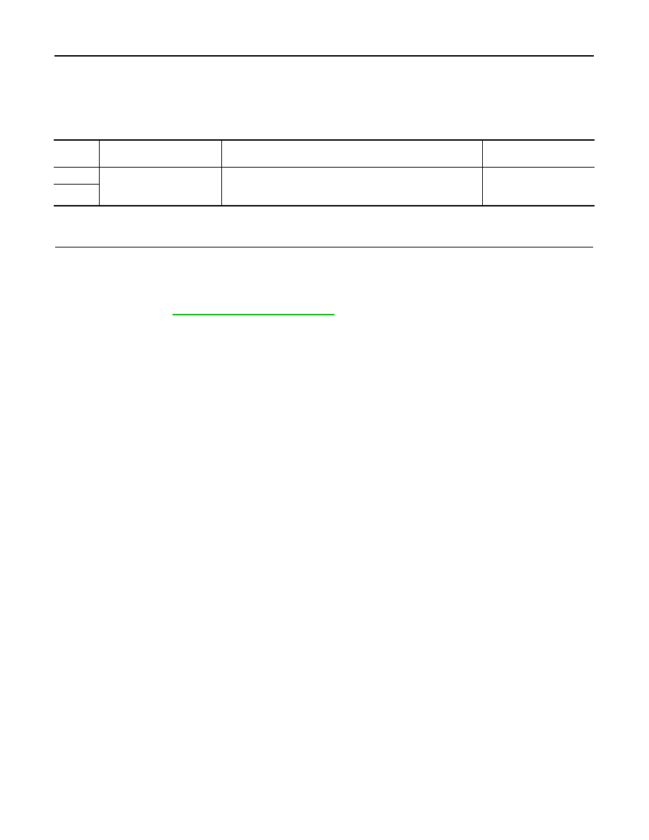
DTC

CONSULT screen terms

(Trouble diagnosis content)

DTC detecting condition

Possible cause

P3172

PD MODULE SYSTEM
(Power Delivery Module sys-
tem)

VCM detects an error signal that is received from PDM (Power 
Delivery Module) via EV system CAN communication.

PDM (Power Delivery 
Module)

P3173

P3175 VCM

EVC-261

< DTC/CIRCUIT DIAGNOSIS >

D

E

F

G

H

I

J

K

L

M

A

B

EVC

N

O

P

P3175 VCM

DTC Logic

INFOID:0000000010120723

DTC DETECTION LOGIC

DTC CONFIRMATION PROCEDURE

1.

PRECONDITIONING

• Turn power switch OFF and wait at least 90 seconds.

CAUTION:

During this period, never perform vehicle handling such as opening and closing of doors. If some

kind of vehicle handling is performed, then wait another 90 seconds or more from the time of the

vehicle handling.

• Make sure that 12V battery voltage is 11 V or more.

>> GO TO 2.

2.

PERFORM DTC CONFIRMATION PROCEDURE

1. Turn power switch ON and wait at least 5 seconds.

2. Check DTC.
Is DTC detected?

YES

>> Proceed to 

EVC-261, "Diagnosis Procedure"

.

NO

>> INSPECTION END

Diagnosis Procedure

INFOID:0000000010120724

1.

REPLACE VCM

Replace the VCM. Refer to 

EVC-423, "Removal and Installation"

.

>> INSPECTION END

DTC

CONSULT screen terms

(Trouble diagnosis content)

DTC detecting condition

Possible cause

P3175

VCM
(VCM)

VCM detects a CAN error signal that is received from electric 
shift control module via CAN communication for 0.1 seconds or 
more.

VCM

EVC-262

< DTC/CIRCUIT DIAGNOSIS >

P3176 TRACTION MOTOR INVERTER CONDENSER

P3176 TRACTION MOTOR INVERTER CONDENSER

DTC Logic

INFOID:0000000010120725

DTC DETECTION LOGIC

NOTE:

If DTC P3176 is displayed with DTC P0A94, P311C, P317A, P3191, P319C, P31A7, P31D4, P31D7, or

P31DD, perform diagnosis for DTC P0A94, P311C, P317A, P3191, P319C, P31A7, P31D4, P31D7, or

P31DD.

DTC CONFIRMATION PROCEDURE

1.

PRECONDITIONING

• Turn power switch OFF and wait at least 90 seconds.

CAUTION:

During this period, never perform vehicle handling such as opening and closing of doors. If some

kind of vehicle handling is performed, then wait another 90 seconds or more from the time of the

vehicle handling.

• Make sure that 12V battery voltage is 11 V or more.

>> GO TO 2.

2.

PERFORM DTC CONFIRMATION PROCEDURE

With CONSULT

1. Set the vehicle to READY and wait at least 10 seconds.

2. Check DTC.
Is DTC detected?

YES

>> Proceed to 

EVC-262, "Diagnosis Procedure"

.

NO

>> INSPECTION END

Diagnosis Procedure

INFOID:0000000010120726

DANGER:

Since hybrid vehicles and electric vehicles contain a high voltage battery, there is the risk of

electric shock, electric leakage, or similar accidents if the high voltage component and vehicle are

handled incorrectly. Be sure to follow the correct work procedures when performing inspection and

maintenance.

WARNING:

• Be sure to remove the service plug in order to disconnect the high voltage circuits before perform-

ing inspection or maintenance of high voltage system harnesses and parts.

• To prevent the removed service plug from being connected by mistake during the procedure, always

carry it in your pocket or put it in the tool box.

• Be sure to wear insulating protective equipment consisting of glove, shoes, face shield and glasses

before beginning work on the high voltage system.

• Clearly identify the persons responsible for high voltage work and ensure that other persons do not

touch the vehicle. When not working, cover high voltage parts with an insulating cover sheet or sim-

ilar item to prevent other persons from contacting them.

• Refer to 

EVC-10, "High Voltage Precautions"

.

CAUTION:

DTC

CONSULT screen terms

(Trouble diagnosis content)

DTC detecting condition

Possible cause

P3176

INVERTER CONDENSER
(Inverter condenser)

Immediately before READY or the start of charge, pre-charging 
cannot be performed for 5 seconds or more. 

• High voltage harness
• LBC
• PDM (Power Delivery 

Module)

• Traction motor inverter
• VCM

P3176 TRACTION MOTOR INVERTER CONDENSER

EVC-263

< DTC/CIRCUIT DIAGNOSIS >

D

E

F

G

H

I

J

K

L

M

A

B

EVC

N

O

P

• Never bring the vehicle into the READY status with the service plug removed unless otherwise

instructed in the Service Manual. A malfunction may occur if this is not observed.

• Erase DTC after the work is completed.

1.

PERFORM SELF-DIAGNOSIS OF VCM

With CONSULT

Perform self-diagnosis of VCM.
Is DTC detected other than P3176?

YES

>> Check the DTC. Refer to 

EVC-102, "DTC Index"

.

NO

>> GO TO 2.

2.

PRECONDITIONING

WARNING:

Disconnect high voltage. Refer to 

GI-33, "How to Disconnect High Voltage"

.

Check voltage in high voltage circuit. (Check that condenser are discharged.)

1. Lift up the vehicle and remove the Li-ion battery under covers. Refer to 

EVB-181, "Exploded View"

.

2. Disconnect high voltage harness connector and PTC heater harness connector from front side of Li-ion

battery. Refer to 

EVB-181, "Removal and Installation"

.

3. Measure voltage between high voltage harness connector terminals and PTC heater harness connector

terminals.

DANGER:


 Touching high voltage components without using the appropriate protective equipment will

cause electrocution.

CAUTION:

For voltage measurements, use a tester which can measure to 500 V or higher.

>> GO TO 3.

3.

CHECK ELECTRIC COMPRESSOR

1. Disconnect electric compressor high voltage harness connector.

2. Check the short circuit between electric compressor terminals.

With heat pump system

Standard

: 5 V or less 

JPCIA0296ZZ

Electric compressor

Resistance

+

Terminal

1

2

3  k

Ω or more


Content   ..  557  558  559  560   ..