Nissan Leaf. Manual - part 546
EVC-208
< DTC/CIRCUIT DIAGNOSIS >
P1805 BRAKE SWITCH
P1805 BRAKE SWITCH
DTC Logic
INFOID:0000000010120660
DTC DETECTION LOGIC
DTC CONFIRMATION PROCEDURE
1.
PERFORM DTC CONFIRMATION PROCEDURE
NOTE:
Since this DTC is difficult to be confirmed, check component function to judge the normality.
>> Proceed to
EVC-208, "Component Function Check"
Component Function Check
INFOID:0000000010120661
1.
CHECK BRAKE SWITCH FUNCTION
With CONSULT
1. On the CONSULT screen, select “EV/HEV” >> “DATA MONITOR” >> “STOP LAMP SW”.
2. Check “STOP LAMP SW” indication under the following conditions.
Is the inspection result normal?
YES
>> INSPECTION END
NO
>> Proceed to
EVC-208, "Diagnosis Procedure"
Diagnosis Procedure
INFOID:0000000010120662
1.
CHECK STOP LAMP SWITCH OPERATION
1. Turn power switch OFF.
2. Check the stop lamp when depressing and releasing the brake pedal.
Is the inspection result normal?
YES
>> GO TO 5.
NO
>> GO TO 2.
2.
CHECK STOP LAMP SWITCH
Check stop lamp switch. Refer to
EVC-209, "Component Inspection (Stop Lamp Switch)"
.
Is the inspection result normal?
YES
>> GO TO 3.
NO
>> Replace stop lamp switch. Refer to
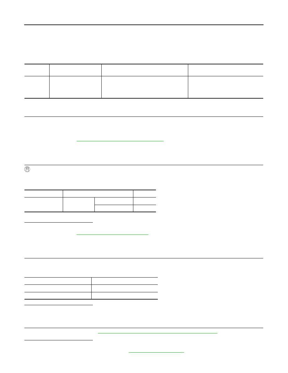
DTC
CONSULT screen terms
(Trouble diagnosis content)
DTC detecting condition
Possible cause
P1805
BRAKE SWITCH
(Brake switch)
Stop lamp signal is not sent to VCM for ex-
tremely long time while the vehicle is driving.
• Harness or connectors
(Stop lamp switch circuit is open or
shorted.)
• Stop lamp switch
Monitor item
Condition
Indication
STOP LAMP SW
Brake pedal
Slightly depressed
ON
Fully released
OFF
Brake pedal
Stop lamp
Fully released
OFF
Slightly depressed
ON