Nissan Leaf. Manual - part 466
 

  Index      Nissan     Nissan Leaf (2011-2014 year) - Service and Repair Manual


Search            


Content   ..  464  465  466  467   ..


Nissan Leaf. Manual - part 466


P33E6 CELL CONTROLLER

EVB-147

< DTC/CIRCUIT DIAGNOSIS >

D

E

F

G

H

I

J

K

L

M

A

B

EVB

N

O

P

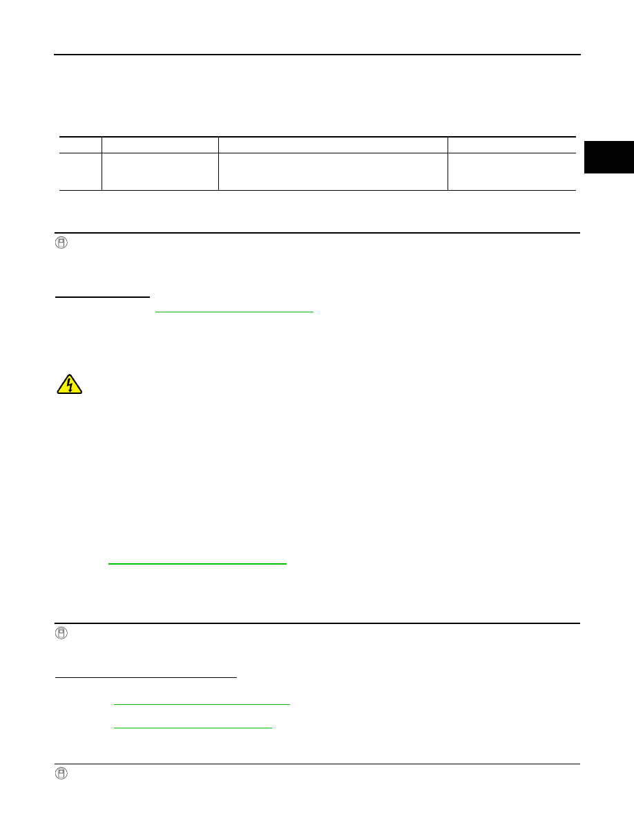
P33E6 CELL CONTROLLER

DTC Logic

INFOID:0000000010121150

DTC DETECTION LOGIC

DTC CONFIRMATION PROCEDURE

1.

PERFORM DTC CONFIRMATION PROCEDURE

With CONSULT

1. Turn power switch ON and wait for 10 seconds or more.

2. Select “Self Diagnostic Result” of “HV BAT”.

3. Check DTC.
Is P33E6 detected?

YES

>> Refer to 

EVB-147, "Diagnosis Procedure"

.

NO

>> INSPECTION END

Diagnosis Procedure

INFOID:0000000010121151

DANGER:

Since hybrid vehicles and electric vehicles contain a high voltage battery, there is the risk of

electric shock, electric leakage, or similar accidents if the high voltage component and vehicle are

handled incorrectly. Be sure to follow the correct work procedures when performing inspection and

maintenance.

WARNING:

• Be sure to remove the service plug in order to disconnect the high voltage circuits before perform-

ing inspection or maintenance of high voltage system harnesses and parts.

• The removed service plug must always be carried in a pocket of the responsible worker or placed in

the tool box during the procedure to prevent the plug from being connected by mistake.

• Be sure to wear insulating protective equipment consisting of glove, shoes, face shield and glasses

before beginning work on the high voltage system.

• Never allow workers other than the responsible person to touch the vehicle containing high voltage

parts. To keep others from touching the high voltage parts, these parts must be covered with an insu-

lating sheet except when using them.

• Refer to 

EVB-7, "High Voltage Precautions"

.

CAUTION:

Never bring the vehicle into the READY status with the service plug removed unless otherwise

instructed in the Service Manual. A malfunction may occur if this is not observed.

1.

CHECK SELF-DIAGNOSIS RESULTS OF LI-ION BATTERY CONTROLLER

With CONSULT

1. Select “Self Diagnostic Result” of “HV BAT”.

2. Check to see if “P0A1F”, “P3062” or “P33ED” is detected simultaneously with “P33E6”.
Is P0A1F, P3062 or P33ED detected?

YES-1 >>  When “P0A1F” or “P3062” are detected simultaneously, Replace Li-ion battery controller. Refer to

EVB-181, "Removal and Installation"

.

YES-2 >> When “P33ED” is detected simultaneously, perform the diagnosis procedure of “P33ED”. Refer to

EVB-156, "Diagnosis Procedure"

.

NO

>> GO TO 2.

2.

CHECK FREEZE FRAME DATA (FFD)

With CONSULT

1. Check “FFD” when DTC is detected.

DTC

Trouble diagnosis name

DTC detecting condition

Possible causes

P33E6

CELL CONTROLLER

With the power switch ON and no load condition, the dif-
ference between the maximum voltage and minimum volt-
age exceeds the allowable range.

• Li-ion battery controller
• Module

EVB-148

< DTC/CIRCUIT DIAGNOSIS >

P33E6 CELL CONTROLLER

2. Calculate the average value of cell voltage by dividing “TOTAL BATTERY VOLTAGE” by 96 (the number

of cells).

3. Identify the minimum cell voltage and the maximum cell voltage from 96 cells.

4. Calculate voltage according to the following expressions to compare voltage between A and B.

Which voltage is larger, A or B?

A

>> Replace module including a cell of the maximum cell voltage. Refer to 

EVB-222, "FRONT MOD-

ULE STACK : Exploded View"

 (Front module stack) or 

EVB-238, "REAR MODULE STACK :

Exploded View"

 (Rear module stack). After replacing module, GO TO 3.

B

>> Replace module including a cell of the minimum cell voltage. Refer to 

EVB-222, "FRONT MOD-

ULE STACK : Exploded View"

 (Front module stack) or 

EVB-238, "REAR MODULE STACK :

Exploded View"

 (Rear module stack). After replacing module, GO TO 3.

3.

PERFORM CELL VOLTAGE LOSS INSPECTION

With CONSULT

1. Select “WORK SUPPORT” of “HV BAT.”

2. Select “CELL VOLTAGE LOSS INSPECTION.” Touch “START.”

3. Check “MINIMUM CELL VOLTAGE.”
Is “MINIMUM CELL VOLTAGE” 3,712 mV or less?

YES

>> GO TO 5.

NO

>> GO TO 4.

4.

DISCHARGE OF LI-ION BATTERY

With CONSULT

1. Set the vehicle to READY.

2. Set the vehicle, according to the following conditions.

3. Check “DATA MONITOR” and let the Li-ion battery discharge until the “MINIMUM CELL VOLTAGE”

reaches 3,712 mV or less.

NOTE:

The guide line is to discharge until the Li-ion battery available charge gauge indicates 2 segments or less.

For discharge time, refer to the following table.

Guideline for discharge time

Average cell voltage = “TOTAL BETTER VOLTAGE” 

÷ 96 (the number of cells)

A = Maximum cell voltage 

 Average cell voltage

B = Average cell voltage 

 Minimum cell voltage

A/C set temperature

: Full hot

A/C fan speed

: Maximum speed

A/C air outlet

: Defroster

Headlamp

: High beam ON

Door glass

: Full open

The number of light-

ing segments of Li-

ion battery available 

charge gauge

Time to 2 segments

12

Approx. 230 minute

11

Approx. 200 minute

10

Approx. 180 minute

9

Approx. 160 minute

8

Approx. 130 minute

7

Approx. 110 minute

6

Approx. 90 minute

P33E6 CELL CONTROLLER

EVB-149

< DTC/CIRCUIT DIAGNOSIS >

D

E

F

G

H

I

J

K

L

M

A

B

EVB

N

O

P

>> GO TO 5.

5.

CHECK CELL OF VOLTAGE LOSS

With CONSULT

1. Check that “MINIMUM CELL VOLTAGE” is 3,712 mV or less. Touch “START.”

2. Check to see if a cell of which voltage is less than or equal to “CELL VOLTAGE LOSS JUDGMENT

VALUE” is displayed.

Is a cell displayed?

YES

>> Record applicable cell No. and then GO TO 6.

NO

>> Check the minimum cell voltage on the data monitor and replace a module which includes the

minimum cell voltage. Refer to 

EVB-222, "FRONT MODULE STACK : Exploded View"

 (Front

module stack) or 

EVB-238, "REAR MODULE STACK : Exploded View"

 (Rear module stack).

6.

PRECONDITIONING

WARNING:

Disconnect high voltage circuit. Refer to 

GI-33, "How to Disconnect High Voltage"

.

1. Remove Li-ion battery. Refer to 

EVB-181, "Removal and Installation"

.

2. Remove battery pack upper case. Refer to 

EVB-190, "BATTERY PACK UPPER CASE : Exploded View"

.

>> GO TO 7.

7.

CHECK CONDENSATION

Check condensation in battery pack.
Is the inspection result normal?

YES

>> GO TO 8.

NO

>> Replace Li-ion battery. Refer to 

EVB-181, "Removal and Installation"

.

8.

CHECK CONNECTORS AND FIXING BOLTS

Check connection state, damage and dust of following;

• Li-ion battery controller (LBC) harness connector

• Module harness connector

• Module terminal fixing bolt
Is the inspection result normal?

YES

>> GO TO 9

NO

>> Repair or replace error-detected parts.

9.

CHECK MODULE VOLTAGE

Check module voltage within determined cell at step 3 and check the divergence of the voltage and cell volt-

age with “DATA MONITOR”.

DANGER:

When check module voltage, be careful not to short.
Is Divergence within 40mV?

YES-1 >> When the determined cell at step 3 is in front module stack.: GO TO 10.

YES-2 >> When the determined cell at step 3 is in rear module stack.: GO TO 12.

NO

>> Replace Li-ion battery controller. Refer to 

EVB-201, "LI-ION BATTERY CONTROLLER : Removal

and Installation"

.

10.

CHECK HARNESS BETWEEN LI-ION BATTERY CONTROLLER AND MODULE HARNESS CONNEC-

5

Approx. 70 minute

4

Approx. 40 minute

3

Approx. 20 minute

The number of light-

ing segments of Li-

ion battery available 

charge gauge

Time to 2 segments

EVB-150

< DTC/CIRCUIT DIAGNOSIS >

P33E6 CELL CONTROLLER

TOR
1. Disconnect Li-ion battery controller harness connector and module harness connector.

2. Check the resistance Li-ion battery controller harness connector and module harness connector of the

determined cell at step 3.

3. Check the divergence of the resistance and the resistance of other cell harness.
Is the inspection result normal?

YES

>> GO TO 11

NO

>> Repair or replace harness or connectors.

11.

CHECK HARNESS BETWEEN MODULE HARNESS CONNECTOR AND BUS BAR

1. Check the resistance module harness connector   and bus bar   of the determined cell at step 3.

2. Check the divergence of the resistance and the resistance of other cell harness.
Is the inspection result normal?

YES

>> Replace module within the determined cell at step 5.

NO

>> Repair or replace harness or connectors.

12.

CHECK HARNESS BETWEEN LI-ION BATTERY CONTROLLER AND BUS BAR

Terminal

Resistance val-

ue

Li-ion battery control-

ler harness connector

Module harness 

connector

Approx. 0 

Terminal

Resistance val-

ue

Module harness con-

nector

Bus bar

Approx. 0 

JSCIA0811GB


Content   ..  464  465  466  467   ..