Nissan Leaf. Manual - part 447
DIAGNOSIS AND REPAIR WORK FLOW
EVB-71
< BASIC INSPECTION >
D
E
F
G
H
I
J
K
L
M
A
B
EVB
N
O
P
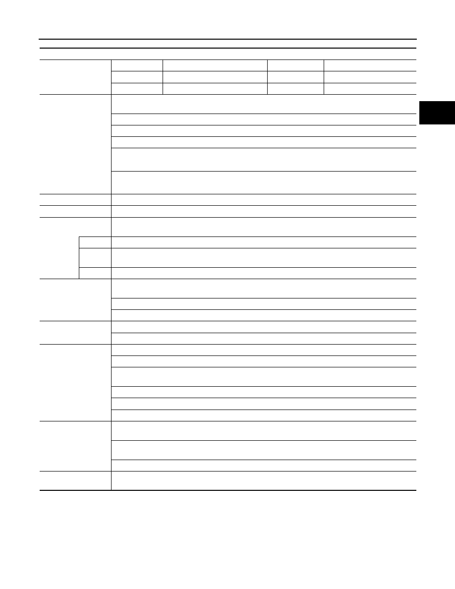
Question Sheet
Customer name
MR/MS
Incident Date
VIN
Model & Year
In Service Date
Trans.
Mileage
km/mile
Symptoms
Does not to READY
EV system warning lamp is on
Power limitation indicator
lamp is on
Water leak*
Noise*
Vibration*
Shock*
Gear noise*
Non driving*
Poor acceleration*
Poor torque*
Radio noise*
Does not charge
Other*
*: If applied, enter in detail
Detailed symptom
Onomatopoeia
Frequency
All the time
Once
Sometimes (
times a day)
Other
Charging condition
Full
Medium
Low
Weather
conditions
Not affected
Weather
Fine
Clouding
Raining
Snowing
Other (
)
Temp.
Hot
Warm
Cool
Cold
Temp. [Approx.
°C
(
°F)]
Humidity
High
Middle
Low
Humidity (Approx.
%)
Road conditions
Not affected
In town
Freeway
Off road (Up / Down)
Deplorable
road
Flat road
While turning (Right / Left)
Bump
Other
Shift position
Not affected
P position
R position
N position
D position
ECO mode
Driving conditions
Not affected
Power switch ON
→ OFF
Power switch OFF
→ ON
READY (stop the vehicle)
While cruis-
ing
While decel-
erating
Just before
stopping
Just after stop-
ping
D position (stop the vehicle)
While recharging
Other
Vehicle speed [
km/h (
MPH)]
Accelerator pedal (
/ 8)
Battery level (Low / Middle / High)
Moments when mal-
function disappears
Disappears while driving
Disappears when stopped
Disappears with select oper-
ation
Disappears when power switch
is pushed OFF
Disappears when battery charge is
stopped
Does not disappear
Other
Other