Nissan Leaf. Manual - part 435


  Index      Nissan     Nissan Leaf (2011-2014 year) - Service and Repair Manual


Search            


Content   ..  433  434  435  436   ..


Nissan Leaf. Manual - part 435


SYSTEM

EVB-23

< SYSTEM DESCRIPTION >

D

E

F

G

H

I

J

K

L

M

A

B

EVB

N

O

P

DESCRIPTION

The Li-ion battery controller (LBC) monitors the status of the inside of the Li-ion battery at all times and sends

information, such as the charging status of Li-ion battery and possible power, to VCM (vehicle control module)

via EV system CAN communication.

The Li-ion battery controller performs control as per the following.

• Monitors the battery state and transfers chargeable/dischargeable power to VCM to prevent an error, such

as overvoltage, over discharge or excessive temperature rise in the battery.

• Detects an error (overvoltage, over discharge, overcurrent, or excessive temperature rise) immediately at

the time of error occurrence and requests VCM to disconnect the system main relay to interrupt the dis-

charge/charge line.

• Maintains the optimum battery state constantly with a cell capacity adjustment function to prevent a reduc-

tion in charging/discharging capacity caused by cell capacity variations.

• Detects the connector fit state with the function to detect the fit of the high voltage harness connector and

transfers the detected state to VCM so that the vehicle does not start with an unsteady state.

• Detects the insulation resistance state with the function to detect the insulation resistance between high and

low voltage and transfers the detected state to VCM so that the vehicle does not start with an unusual state.

• Estimates a battery charge state and low battery state, based on the data obtained with the battery state

detection function, and reflects on the battery capacity meter.

BATTERY PROTECTION

The Li-ion battery has a voltage range capable of charge/discharge. If charged/discharged exceeding the

range, excessive low capacity or malfunction may be caused. To prevent this, the Li-ion battery controller

detects voltage of each cell and requests the control of charging/discharging energy to VCM so that the cell

voltage stays within the voltage range.
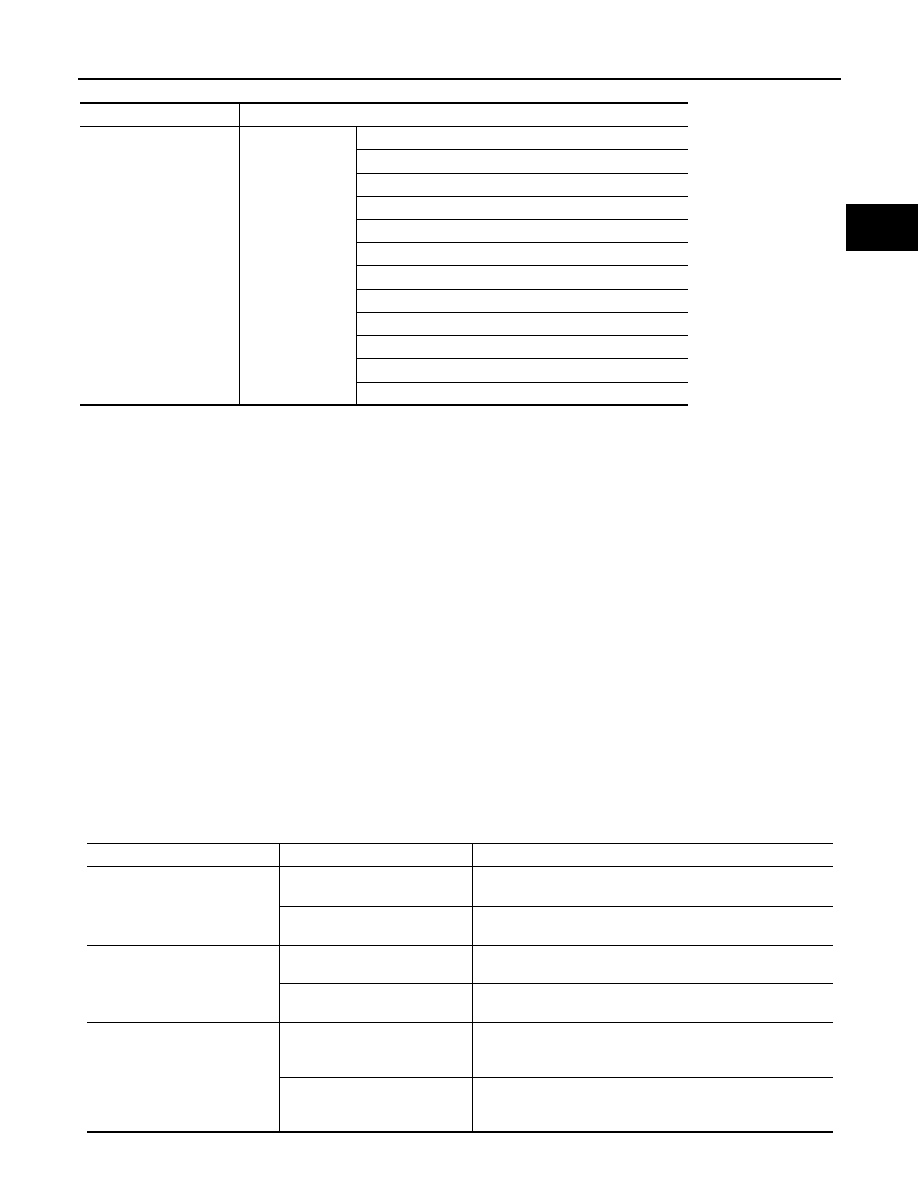
Received unit

Signal name

VCM

EV system CAN

High voltage discharge permit signal

Li-ion battery main relay cut request signal

Li-ion battery connector interlock signal

Li-ion battery voltage signal

Li-ion battery current signal

Li-ion battery chargeable power signal

Li-ion battery dischargeable power signal

Li-ion battery chargeable completion signal

Li-ion battery available charge signal

Li-ion battery capacity signal

Li-ion battery gradual capacity loss signal

Insulation resistance signal

Control item

Control

Operating condition

Overvoltage/overcurrent protec-
tion

Charging energy control

Gradual control of charging energy as the cell voltage ap-
proaches the upper limit of the voltage capable of charging.

System main relay cut

Cell voltage exceeds the voltage judged as overvoltage and 
maintains the voltage for more than the specified time.

Over discharge protection

Discharging energy control

Gradual control of discharging energy as the cell voltage ap-
proaches the lower limit of the voltage capable of discharging.

System main relay cut

Cell voltage exceeds the voltage judged as over discharge and 
maintains the voltage for more than the specified time.

Excessive temperature rise pro-
tection

Charging/discharging energy 
control

Gradual control of charging/discharging energy as Li-ion bat-
tery temperature approaches the upper limit of the temperature 
capable of use.

System main relay cut

Li-ion battery temperature exceeds the temperature judged as 
excessive temperature rise and maintains the temperature for 
more than the specified time.

EVB-24

< SYSTEM DESCRIPTION >

SYSTEM

HOW TO ADJUST CELL CAPACITY

During cell capacity adjustment, the capacity of each cell is estimated based on the no-load voltage when the

system starts, and the capacities are adjusted so that they are all at the target level. The voltage of each cell is

detected inside the Li-ion battery controller. The bypass switches are then turned ON to discharge the cells

that have excess capacity. In this way, capacity adjustment by the Li-ion battery controller allows the capacity

of all cells to be fully utilized.

INSULATION RESISTANCE LOSS DETECTION FUNCTION

The insulation resistance detection circuit mounted inside the Li-ion battery controller measures the insulation

resistance of each high voltage part and sends the measurement results to VCM via EV system CAN commu-

nication.

VCM judges abnormal insulation resistance in each high voltage part, based on the received insulation resis-

tance value.

LI-ION BATTERY HEATER CONTROL SYSTEM

JPCIA0094GB

JSCIA0732GB

SYSTEM

EVB-25

< SYSTEM DESCRIPTION >

D

E

F

G

H

I

J

K

L

M

A

B

EVB

N

O

P

LI-ION BATTERY HEATER CONTROL SYSTEM : System Description

INFOID:0000000010121040

SYSTEM DIAGRAM

INPUT/OUTPUT SIGNAL ITEM

Input Signal Item

Output Signal Item

DESCRIPTION

• When the temperature decreases [approximately 

−20°C (−4°F)] extremely in the battery pack, the Li-ion bat-

tery heater control system automatically activates the Li-ion battery heater to warm the inside of the battery

pack for protecting Li-ion battery from freezing and preventing the decline in battery output. In addition, when

the temperature in the battery pack is restored [approximately 

−10°C (14°F)], the Li-ion battery heater stops.

• The Li-ion battery controller (LBC) detects a temperature in the battery pack, according to a signal transmit-

ted from the battery temperature sensor installed to the battery pack and judges the activation of the Li-ion

battery heater.

• When the relay built in the heater relay unit turns ON, high voltage power is supplied to each Li-ion battery

heater.

• LBC detects the ON/OFF status of the relay built in to heater relay unit.

• Even when the power switch is OFF, VCM periodically activates LBC to protect Li-ion battery from freezing.

JSCIA0793GB

Transmit unit

Signal name

VCM

EV system CAN communication

Keep SOC request signal

Receive unit

Signal name

VCM

EV system CAN communication

Next start time signal

EVB-26

< SYSTEM DESCRIPTION >

SYSTEM

• When the temperature in Li-ion battery pack is low with no necessity of Li-ion battery heater operation, LBC

estimates the time that Li-ion battery may freeze and transmits a next start time signal to VCM via EV sys-

tem CAN communication to prepare for starting the Li-ion battery heater next time.

• When receiving a next start time signal via EV system CAN communication, VCM transmits a start request

signal (CHG-IGN) to LBC after a lapse of the set time. When receiving a start request signal (CHG-IGN),

LBC activates the Li-ion battery heater.

When EVSE is connected (normal charge)

• When the temperature in the battery pack is low outside the timer charge set time, VCM transmits a keep

SOC request signal to LBC via EV system CAN communication. In this case Li-ion battery is not charged,

and only Li-ion battery heater is activated. 

• When timer charge starts at the set time, Li-ion batter is charged, and the Li-ion battery heater is activated.

When EVSE is not connected (normal charge)

• When the charge level of the Li-ion battery is low during the Li-ion battery heater operation, LBC stops the

Li-ion battery heater operation even if the temperature in the battery pack is insufficient. 

JSCIA0430ZZ

JSCIA0431ZZ


Content   ..  433  434  435  436   ..