Nissan Leaf. Manual - part 310


  Index      Nissan     Nissan Leaf (2011-2014 year) - Service and Repair Manual


Search            


Content   ..  308  309  310  311   ..


Nissan Leaf. Manual - part 310


BRC-30

< SYSTEM DESCRIPTION >

[WITH VDC]

SYSTEM

*1: Communication line between yaw rate/side/decel G sensor and ABS actuator and electric unit (control unit)

*2: CAN communication line between electrically-driven intelligent brake unit and ABS actuator and electric

unit (control unit)

OPERATION CHARACTERISTICS

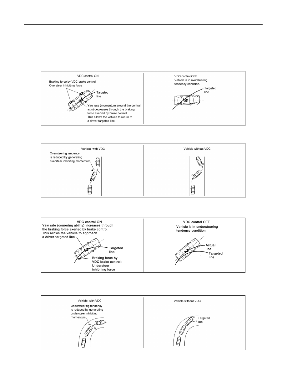
VDC Function That Prevents Oversteer Tendency

• During a cornering, brake force (brake fluid pressure) is applied on front wheel and rear wheel on the outer

side of turn. Momentum directing towards the outer side of turn is generated. Oversteer is prevented.

• Changing driving lane on a slippery road, when oversteer tendency is judged large, motor torque is con-

trolled as well as brake force (brake fluid pressure) of 4 wheels. Oversteer tendency decreases.

VDC Function That Prevents Understeer Tendency

• During a cornering, brake force (brake fluid pressure) is applied on front wheel and rear wheel on the inner

side of turn. Momentum directing towards the inner side of turn is generated. Understeer is prevented.

• Applying braking during a cornering on a slippery road, when understeer tendency is judged large, motor

torque is controlled as well as brake force (brake fluid pressure) of four wheels. Understeer tendency

decreases.

TCS FUNCTION

ALFIA0339GB

ALFIA0340GB

JPFIC0137GB

ALFIA0341GB

SYSTEM

BRC-31

< SYSTEM DESCRIPTION >

[WITH VDC]

C

D

E

G

H

I

J

K

L

M

A

B

BRC

N

O

P

TCS FUNCTION : System Description

INFOID:0000000010120033

• Wheel spin status of drive wheel is detected by wheel sensor of 4

wheels. Motor torque is controlled so that slip rate of drive wheels

is in appropriate level. When wheel spin occurs on drive wheel,

ABS actuator and electric unit (control unit) perform brake force

control of LH and RH drive wheels (apply brake force by increasing

brake fluid pressure of drive wheel) and decrease motor torque by

motor torque control. Wheel spin amount decreases. Motor torque

is controlled to appropriate level.

• TCS function can be switched to non-operational status (OFF) by

operating VDC OFF switch. In this case, VDC OFF indicator lamp

turns ON.

• VDC warning lamp blinks while TCS function is in operation and

indicates to the driver that the function is in operation.

• CONSULT can be used to diagnose the system diagnosis.

• Fail-safe function is adopted. When a malfunction occurs in TCS function, the control is suspended for VDC

function, TCS function, brake limited slip differential (BLSD) function and brake assist function. The vehicle

status becomes the same as models without VDC function, TCS function, brake limited slip differential

(BLSD) function and brake assist function. However, ABS function and EBD function are operated normally.

Refer to 

BRC-53, "Fail-safe"

.

SYSTEM DIAGRAM

INPUT SIGNAL AND OUTPUT SIGNAL

Major signal transmission between each unit via communication lines is shown in the following table.

JSFIA0781GB

JSFIA2065GB

BRC-32

< SYSTEM DESCRIPTION >

[WITH VDC]

SYSTEM

*1: Communication line between yaw rate/side/decel G sensor and ABS actuator and electric unit (control unit)

*2: CAN communication line between electrically-driven intelligent brake unit and ABS actuator and electric

unit (control unit)

ABS FUNCTION
ABS FUNCTION : System Description

INFOID:0000000010120034

• By preventing wheel lock through brake force (brake fluid pressure) control that is electronically controlled by

detecting wheel speed during braking, stability during emergency braking is improved so that obstacles can

be easily bypassed by steering operation.

• During braking, control units calculates wheel speed and pseudo-vehicle speed, and transmits pressure

increase, hold or decrease signals to actuator portion according to wheel slip status.

Component

Signal description

Yaw rate/side/decel G sensor

Mainly transmits the following signals to ABS actuator and electric unit (control unit) via com-
munication line

*1:

• Yaw rate signal
• Side G sensor signal
• Decel G sensor signal

VCM

Mainly transmits the following signals to ABS actuator and electric unit (control unit) via CAN 
communication:
• Accelerator pedal position signal
• VCM control signal
• Shift position signal

Electrically-driven intelligent brake

Mainly transmits the following signals to ABS actuator and electric unit (control unit) via CAN 
communication line

*2

:

• Electrically-driven intelligent brake control signal
• Brake warning lamp request signal
• Brake system warning lamp request signal

Steering angle sensor

Mainly transmits the following signal to ABS actuator and electric unit (control unit) via CAN 
communication:
• Steering angle sensor signal

Combination meter

Mainly transmits the following signals to ABS actuator and electric unit (control unit) via CAN 
communication:
• Brake fluid level switch signal
• Parking brake switch signal
Mainly receives the following signals from ABS actuator and electric unit (control unit) via CAN 
communication:
• ABS warning lamp signal
• VDC warning lamp signal
• Brake warning lamp signal
• Brake system warning lamp signal
• VDC OFF indicator lamp signal

SYSTEM

BRC-33

< SYSTEM DESCRIPTION >

[WITH VDC]

C

D

E

G

H

I

J

K

L

M

A

B

BRC

N

O

P

• The following effects are obtained by preventing wheel lock during

braking:

- Vehicle tail slip is prevented during braking when driving straight.

- Understeer and oversteer tendencies are moderated during brak-

ing driving on a corner.

- Obstacles may be easily bypassed by steering operation during

braking.

• CONSULT can be used to diagnose the system diagnosis.

• Fail-safe function is adopted. When a malfunction occurs in ABS

function, the control is suspended for VDC function, TCS function,

ABS function, brake limited slip differential (BLSD) function and

brake assist function. The vehicle status becomes the same as

models without VDC function, TCS function, ABS function, brake

limited slip differential (BLSD) function and brake assist function.

However, EBD function is operated normally. Refer to 

BRC-53,

"Fail-safe"

.

NOTE:

• ABS has the characteristic as described here, but it is not the

device that helps reckless driving.

• To stop vehicle efficiently, ABS does not operate and ordinary

brake operates at low speed [approx. 10 km/h (6.2 MPH) or less,

but differs subject to road conditions).

• Self-diagnosis is performed immediately after when motor starts

and when vehicle initially is driven [by vehicle speed approx. 15

km/h (9.3 MPH)]. Motor sounds are generated during self-diagnosis. In addition, brake pedal may be felt

heavy when depressing brake pedal lightly. These symptoms are not malfunctions.

SYSTEM DIAGRAM

INPUT SIGNAL AND OUTPUT SIGNAL

Major signal transmission between each unit via communication lines is shown in the following table.

JPFIC0140GB

JPFIC0144GB


Content   ..  308  309  310  311   ..