Nissan Leaf. Manual - part 177


  Index      Nissan     Nissan Leaf (2011-2014 year) - Service and Repair Manual


Search            


Content   ..  175  176  177  178   ..


Nissan Leaf. Manual - part 177


DIAGNOSIS SYSTEM (ELECTRICALLY-DRIVEN INTELLIGENT BRAKE UNIT)

BR-29

< SYSTEM DESCRIPTION >

C

D

E

G

H

I

J

K

L

M

A

B

BR

N

O

P

DIAGNOSIS SYSTEM (ELECTRICALLY-DRIVEN INTELLIGENT BRAKE
UNIT)

CONSULT Function

INFOID:0000000010122993

APPLICATION ITEM

CONSULT can display each diagnostic item using the diagnostic test modes as follows.

*: The following diagnosis information is erased by erasing.

CAUTION:

After erasing self-diagnosis results, turn the power switch OFF to exit CONSULT, and disconnect CON-

SULT from data link connector. Close all doors (including back door), check that the room lamp is OFF,

get out of the vehicle, and wait for 3 minutes or more with all doors closed. Never operate the vehicle

while waiting.

• DTC

• Freeze frame data (FFD)

ECU IDENTIFICATION

Electrically-driven intelligent brake unit part number can be read.

SELF DIAGNOSTIC RESULT

Refer to 

BR-38, "DTC Index"

.

When “CRNT” is displayed on self-diagnosis result

• The system is presently malfunctioning.

When “PAST” is displayed on self-diagnosis result

• System malfunction in the past is detected, but the system is presently normal.

Freeze frame data (FFD)

When DTC is detected, a vehicle state shown below is recorded and displayed on CONSULT.
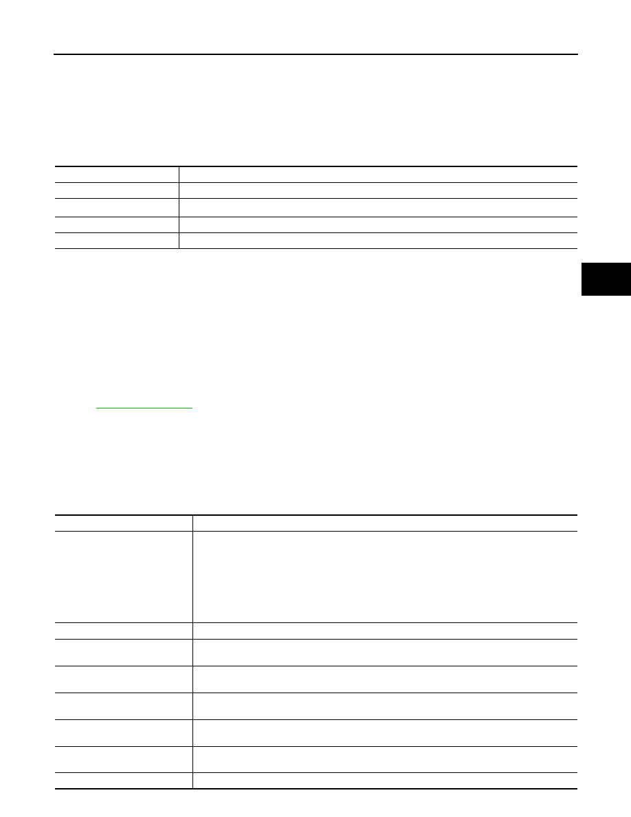
Mode

Function description

ECU identification

Parts number of electrically-driven intelligent brake unit can be read.

Self Diagnostic Results

Self-diagnostic results and freeze frame data can be read and erased quickly.

*

DATA MONITOR

Input/Output data in the electrically-driven intelligent brake unit can be read.

Work Support

Components can be quickly and accurately adjusted.

Item name

Display item

IGN counter
(0 

− 39)

The number of times that power switch is ON after the DTC is detected is displayed.
• When “0” is displayed: It indicates that the system is presently malfunctioning.
• When except “0” is displayed: It indicates that system malfunction in the past is detected, but the 

system is presently normal.
NOTE:
Each time when power switch is turned OFF to ON, numerical number increases in 1 

→ 2 → 

3...38 

→ 39. When the operation number of times exceeds 39, the number do not increase and 

“39” is displayed until self-diagnosis is erased.

PEDAL STROKE VALUE

Displays the brake pedal stroke at the time the malfunction is detected.

MASTER CYL PRESSURE

Displays the brake fluid pressure generated in the master cylinder at the time the malfunction is 
detected.

CONTROL MODULE TEMP

Displays the temperature of the control module that is integrated with the electrically-driven intelli-
gent brake unit at the time the malfunction is detected.

MOTOR POWER SUPPLY

Displays the power voltage of the motor inside the electrically-driven intelligent brake unit at the 
time the malfunction is detected.

CONTROL MODULE POWER

Displays the power voltage of the control module that is integrated with the electrically-driven intel-
ligent brake unit at the time the malfunction is detected.

Q axis current

Displays the current at the motor inside the electrically-driven intelligent brake unit at the time the 
malfunction is detected.

VEHICLE SPEED

Displays the vehicle speed at the time the malfunction is detected.

BR-30

< SYSTEM DESCRIPTION >

DIAGNOSIS SYSTEM (ELECTRICALLY-DRIVEN INTELLIGENT BRAKE UNIT)

*: When one or more doors including the back door are open: “DOOR OPEN” is displayed. When all doors

including the back door are closed: “DOOR CLOSE” is displayed.

DATA MONITOR

NOTE:

The following table includes information (items) inapplicable to this vehicle. For information (items) applicable

to this vehicle, refer to CONSULT display items.

DECEL G SENSOR

Displays the decel G at the time the malfunction is detected.

ACTUAL GEAR POSITION

Displays the shift position at the time the malfunction is detected.

MILEAGE

 Displays the mileage at the time the malfunction is detected.

SYSTEM OPERATING TIME 
(msec)

Time between the start of the electrically-driven intelligent brake unit and DTC detection is dis-
played by “msec”.

SYSTEM OPERATING TIME 
(min)

 Time between the start of the electrically-driven intelligent brake unit and DTC detection is dis-
played by “min”.

BACKUP UNIT OUT VOLT

 Displays the power voltage of the brake power supply backup unit at the time the malfunction is 
detected.

WAKEUP SIGNAL STATUS

IGN ON

Displayed if the power switch is ON when DTC is detected.

IGN OFF

Displayed if the power switch is in a state other than ON when 
DTC is detected.

STOP LAMP SW ON

Displayed if the brake pedal is depressed when DTC is detect-
ed.

STOP LAMP SW OFF

Displayed if the brake pedal is not depressed when DTC is de-
tected.

DOOR OPEN

Displayed if the driver's door is open when DTC is detected.

DOOR CLOSE

Displayed if the driver's door is close when DTC is detected.

SLEEP

Displayed if the electrically-driven intelligent brake unit is not 
active when DTC is detected.

WAKE UP

Displayed if the electrically-driven intelligent brake unit is ac-
tive when DTC is detected.

READY ON

Displayed if the vehicle is in READY state when DTC is detect-
ed.

READY OFF

Displayed if the vehicle is in a state other than READY state 
when DTC is detected.

CAN COMM ON

Displayed if CAN communication is performed when DTC is 
detected.

CAN COMM OFF

Displayed if CAN communication is not performed when DTC 
is detected.

IGNITION SIGNAL

Displays the status of ignition switch at the time a DTC is detected.

STATUS STOP LAMP SW

Displays the status of brake pedal operation at the time a DTC is detected.

DOOR SWITCH

Displays the status of all doors (including back the door) at the time a DTC is detected.

*

COMMAND WAKE UP SLEEP

Displays the status of the start-up permit of the electrically driven intelligent brake unit at the time 
a DTC is detected.

STATUS READY

Displays the status of READY where a DTC is detected.

CONDITION CAN DIAG PERMIS Displays the status of the CAN communication diagnosis permit at the time a DTC is detected.

Item name

Display item

Item (Unit)

Note:

MASTER CYL PRESSURE
(V)

Master cylinder pressure sensor voltage is displayed.

MASTER CYL PRES (VDC)
(MPa)

Displays the fluid pressure of master cylinder part.

DIAGNOSIS SYSTEM (ELECTRICALLY-DRIVEN INTELLIGENT BRAKE UNIT)

BR-31

< SYSTEM DESCRIPTION >

C

D

E

G

H

I

J

K

L

M

A

B

BR

N

O

P

MOTOR TEMPERATURE
(

°F)

Displays the temperature of the motor inside the electrically-driven intelligent brake unit.

CONTROL MODULE TEMP
(

°F)

Displays the temperature of the control module that is integrated with the electrically-driven 
intelligent brake unit.

MST CYL PRES POWER VOLT
(V)

Master cylinder pressure sensor power supply is displayed

STROKE SEN 1 POWERT VOLT
(V)

Stroke sensor 1* output power supply is displayed

MOTOR POWER SUPPLY
(V)

Displays the power supply voltage of the motor inside the electrically-driven intelligent 
brake unit.

CONTROL MODULE POWER
(V)

Displays the power supply voltage of the control module that is integrated with the electri-
cally-driven intelligent brake unit.

STROKE SEN 1 LEARN VALUE
(deg)

Displays the stroke sensor 1

*

 learning value.

STROKE SEN 2 LEARN VALUE
(deg)

Displays the stroke sensor 2

*

 learning value.

STROKE SEN 1 OUTPUT VOLT
(V)

Displays the stroke sensor 1

*

 output voltage.

ALL SENSOR LEARNING
(INCOMP/COMP)

Displays the learning values of stroke sensor 1

*

, stroke sensor 2

*

, and master cylinder 

pressure.

STEERING ANGLE SENSOR
(deg)

Displays the steering angle.

DECEL G SENSOR
(G)

Displays the decel G.

SIDE G SENSOR
(G)

Displays the side G.

YAW RATE SENSOR SIGNAL
(deg/s)

Displays the yaw rate.

WHEEL SENSOR FRONT RH
(rpm)

Displays the front RH wheel speed.

WHEEL SENSOR FRONT LH
(rpm)

Displays the front LH wheel speed.

WHEEL SENSOR REAR RH
(rpm)

Displays the rear RH wheel speed.

WHEEL SENSOR REAR LH
(rpm)

Displays the rear LH wheel speed.

VEHICLE SPEED
(km/h)

Displays the vehicle speed.

ACTUAL GEAR POSITION
[D/R/(N/P)]

Displays the shift position.

BRAKE SWITCH
(On/Off)

Displays the operating status of stop lamp switch.

COMMAND WAKE UP SLEEP
(SLEEP/WAKEUP)

Displays the wake up status.

DOOR SWITCH
(CLOSE/OPEN)

Displays the status of door.

IGNITION SIGNAL
(On/Off)

Displays the status of power switch.

VCM STATUS
(On/Off)

Displays the VCM status.

Item (Unit)

Note:

BR-32

< SYSTEM DESCRIPTION >

DIAGNOSIS SYSTEM (ELECTRICALLY-DRIVEN INTELLIGENT BRAKE UNIT)

*: The stroke sensor is composed of two circuits: stroke sensor 1 and stroke sensor 2.

WORK SUPPORT

BACKUP UINT DIAG RESULT
(NORMAL/ERR1/ERR2/ERR3/ERR4/
ERR5/ERR6/ERR7/ERR8/ERR9/ERR10/
ERR11/ERR12/ERR13/ERR14/ERR15)

Displays the diagnosis results for the brake power supply backup unit.

BACKUP UNIT MODE
(On/Off)

Displays the operating status of the brake power supply backup unit.

BACKUP UNIT CHG STATUS
(CHG1/CHG2/FULL)

Displays the charge status of the brake power supply backup unit.

DRV TRQ CTRL VAL
(Nm)

Displays a correction value for minutely increasing/decreasing the drive torque.

DRV TRQ CTRL MODE
(NOMAL/ERR1/ERR2/ERR3)

Displays a correction state of minutely increasing/decreasing the drive torque.

DRV TRQ CTRL STP FLAG
(PERMIS/CANCEL)

Displays the permission/cancellation to a correction for minutely increasing/decreasing the 
drive torque.

Item (Unit)

Note:

Item

Description

STROKE SENSOR 0 POINT LEARNING

Perform stroke sensor learning.


Content   ..  175  176  177  178   ..