Nissan Leaf. Manual - part 1194


  Index      Nissan     Nissan Leaf (2011-2014 year) - Service and Repair Manual


Search            


Content   ..  1192  1193  1194  1195   ..


Nissan Leaf. Manual - part 1194


P0A8D 14VOLT POWER VOLTAGE

TMS-57

< DTC/CIRCUIT DIAGNOSIS >

D

E

F

G

H

I

J

K

L

M

A

B

TMS

N

O

P

P0A8D 14VOLT POWER VOLTAGE

DTC Logic

INFOID:0000000010120942

DTC DETECTION LOGIC

DTC CONFIRMATION PROCEDURE

1.

PRECONDITIONING

If “DTC CONFIRMATION PROCEDURE” has been previously conducted, always power switch OFF and wait

at least 10 seconds before conducting the next test.

>> GO TO 2.

2.

CHECK DTC DETECTION

With CONSULT

1. Power switch ON and wait 10 seconds or more.

2. Check DTC.
Is “P0A8D” detected?

YES

>> Go to 

TMS-57, "Diagnosis Procedure"

.

NO-1 >> To check malfunction symptom before repair: Refer to 

GI-53, "Intermittent Incident"

.

NO-2 >> Confirmation after repair: INSPECTION END

Diagnosis Procedure

INFOID:0000000010120943

1.

CHECK TRACTION MOTOR INVERTER HARNESS CONNECTOR

1. Power switch OFF.

2. Check the connection conditions of the traction motor inverter harness connector.
Is the inspection result normal?

YES

>> GO TO 2.

NO

>> Repair or replace damaged parts.

2.

CHECK POWER SUPPLY CIRCUIT

1. Disconnect the traction motor inverter harness connector.

2. Check the 10A fuse (#74).

3. Power switch ON.

4. Check the voltage between traction motor inverter vehicle side harness connector terminals.

Is the inspection result normal?

YES

>> Replace the traction motor inverter. Refer to 

TMS-103, "Removal and Installation"

.

NO

>> Check the M/C relay. Refer to 

EVC-371, "Diagnosis Procedure"
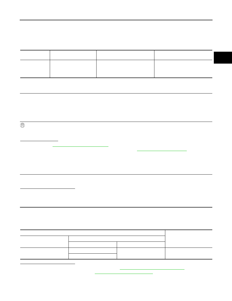
.

DTC

CONSULT screen terms

(Trouble diagnosis content)

Malfunction detected condition

Possible causes

P0A8D

14VOLT POWER VOLTAGE
(14 Volt Power Module System 
Voltage Low)

The voltage of 12V battery drops to ap-
prox. 8 V or less

• Harness, fuse,  or connectors

(Each circuit is open or shorted.)

• Traction motor inverter
• M/C relay

Traction motor inverter

Voltage

Connector

Terminal

+

F13

46

47, 49

9 – 16 V

48

TMS-58

< DTC/CIRCUIT DIAGNOSIS >

P0BE5 D-MOTOR A PHASE U CURRENT SEN

P0BE5 D-MOTOR A PHASE U CURRENT SEN

DTC Logic

INFOID:0000000010120944

DTC DETECTION LOGIC

DTC CONFIRMATION PROCEDURE

1.

PRECONDITIONING

If “DTC CONFIRMATION PROCEDURE” has been previously conducted, always power switch OFF and wait

at least 10 seconds before conducting the next test.

>> GO TO 2.

2.

CHECK DTC DETECTION

With CONSULT

1. Power switch ON and wait for 10 seconds or more.

2. Check DTC.
Is “P0BE5” detected?

YES

>> Go to 

TMS-60, "Diagnosis Procedure"

.

NO-1 >> To check malfunction symptom before repair: Refer to 

GI-53, "Intermittent Incident"

.

NO-2 >> Confirmation after repair: INSPECTION END

Diagnosis Procedure

INFOID:0000000010120945

1.

REPLACE TRACTION MOTOR INVERTER

Replace the traction motor inverter. Refer to 

TMS-103, "Removal and Installation"

.

>> END

DTC

CONSULT screen terms

(Trouble diagnosis content)

Malfunction detected condition

Possible cause

P0BE5

D-MOTOR A PHASE U CURRENT SEN
(Drive Motor “A” Phase U Current Sen-
sor Circuit)

Detection values differ between the current 
sensors (inner sensor 1 and 2) of the tranc-
tion motor U-phase

Traction motor inverter

P0BE6 D-MOTOR A PHASE U CURRENT SEN

TMS-59

< DTC/CIRCUIT DIAGNOSIS >

D

E

F

G

H

I

J

K

L

M

A

B

TMS

N

O

P

P0BE6 D-MOTOR A PHASE U CURRENT SEN

DTC Logic

INFOID:0000000010120946

DTC DETECTION LOGIC

DTC CONFIRMATION PROCEDURE

1.

PRECONDITIONING

If “DTC CONFIRMATION PROCEDURE” has been previously conducted, always power switch OFF and wait

at least 10 seconds before conducting the next test.

>> GO TO 2.

2.

CHECK DTC DETECTION

With CONSULT

1. Power switch ON and wait for 10 seconds or more.

2. Check DTC.
Is “P0BE6” detected?

YES

>> Go to 

TMS-59, "Diagnosis Procedure"

.

NO-1 >> To check malfunction symptom before repair: Refer to 

GI-53, "Intermittent Incident"

.

NO-2 >> Confirmation after repair: INSPECTION END

Diagnosis Procedure

INFOID:0000000010120947

1.

REPLACE TRACTION MOTOR INVERTER

Replace the traction motor inverter. Refer to 

TMS-103, "Removal and Installation"

.

>> END

DTC

CONSULT screen terms

(Trouble diagnosis content)

Malfunction detected condition

Possible cause

P0BE6

D-MOTOR A PHASE U CURRENT SEN
(Drive Motor “A” Phase U Current Sen-
sor Circuit Range/Performance)

If the value detected by the traction motor U-
phase current sensor is abnormal

Traction motor inverter

TMS-60

< DTC/CIRCUIT DIAGNOSIS >

P0BE9 D-MOTOR A PHASE V CURRENT SEN

P0BE9 D-MOTOR A PHASE V CURRENT SEN

DTC Logic

INFOID:0000000010120948

DTC DETECTION LOGIC

DTC CONFIRMATION PROCEDURE

1.

PRECONDITIONING

If “DTC CONFIRMATION PROCEDURE” has been previously conducted, always power switch OFF and wait

at least 10 seconds before conducting the next test.

>> GO TO 2.

2.

CHECK DTC DETECTION

With CONSULT

1. Power switch ON and wait for 10 seconds or more.

2. Check DTC.
Is “P0BE9” detected?

YES

>> Go to 

TMS-60, "Diagnosis Procedure"

.

NO-1 >> To check malfunction symptom before repair: Refer to 

GI-53, "Intermittent Incident"

.

NO-2 >> Confirmation after repair: INSPECTION END

Diagnosis Procedure

INFOID:0000000010120949

1.

REPLACE TRACTION MOTOR INVERTER

Replace the traction motor inverter. Refer to 

TMS-103, "Removal and Installation"

.

>> END

DTC

CONSULT screen terms

(Trouble diagnosis content)

Malfunction detected condition

Possible cause

P0BE9

D-MOTOR A PHASE V CURRENT SEN
(Drive Motor “A” Phase V Current Sen-
sor Circuit)

Detection values differ between the current 
sensors (inner sensor 1 and 2) of the trac-
tion motor V-phase

Traction motor inverter


Content   ..  1192  1193  1194  1195   ..