Content .. 1175 1176 1177 1178 ..
Nissan Leaf. Manual - part 1177
TM-114
< DTC/CIRCUIT DIAGNOSIS >
[ELECTRIC SHIFT]
U1010 CONTROL UNIT (CAN)
U1010 CONTROL UNIT (CAN)
DTC Logic
INFOID:0000000010119634
DTC DETECTION LOGIC
DTC CONFIRMATION PROCEDURE
1.
PREPARATION BEFORE WORK
If another "DTC CONFIRMATION PROCEDURE" occurs just before, power switch OFF and wait for at least
10 seconds, then perform the next test.
>> GO TO 2.
2.
PERFORM DTC CONFIRMATION PROCEDURE
With CONSULT
1. Power switch OFF to ON and wait for 5 seconds or more.
2. Check DTC.
Is “U1010” detected?
YES
>> Go to
NO-1 >> To check malfunction symptom before repair: Refer to
GI-53, "Intermittent Incident"
.
NO-2 >> Confirmation after repair: INSPECTION END
Diagnosis Procedure
INFOID:0000000010119635
1.
REPLACE VCM
Replace the VCM due to malfunction in the electric shift control module built in VCM. Refer to
.
>> END
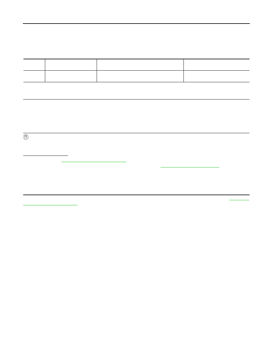
DTC
CONSULT screen terms
(Trouble diagnosis content)
DTC detection condition
Possible cause
U1010
CONTROL UNIT (CAN)
(Control Module Malfunction)
Malfunction is detected in the CAN communication
initial diagnosis (control module malfunction).
Electric shift control module