Nissan Leaf. Manual - part 1142


  Index      Nissan     Nissan Leaf (2011-2014 year) - Service and Repair Manual


Search            


Content   ..  1140  1141  1142  1143   ..


Nissan Leaf. Manual - part 1142


EPS CONTROL UNIT

STC-13

< ECU DIAGNOSIS INFORMATION >

C

D

E

F

H

I

J

K

L

M

A

B

STC

N

O

P

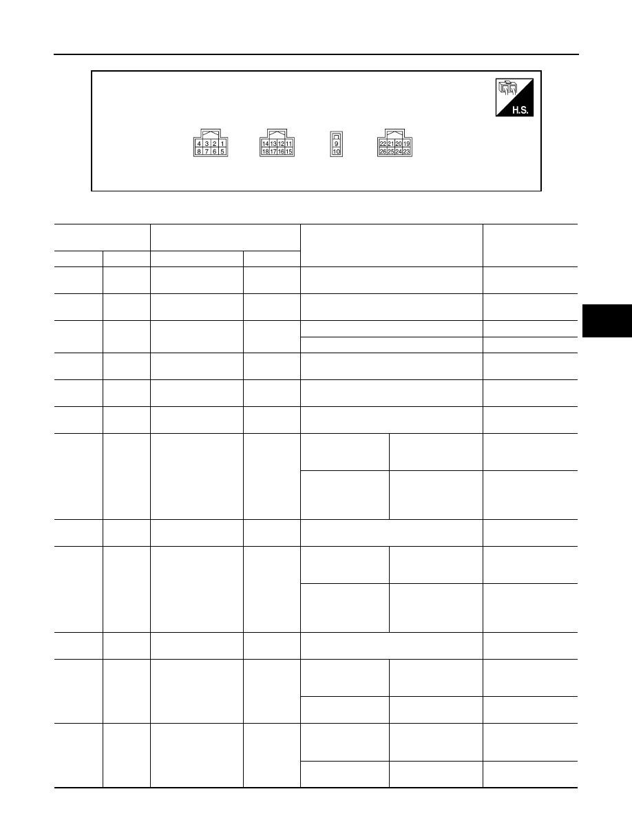
TERMINAL LAYOUT

PHYSICAL VALUES

ALGIA0178ZZ

Terminal No.

(Wire Color)

Description

Condition

Value

(Approx.)

+

Signal name

Input/Output

1

(P)

CAN-L

Input/Output

2

(L)

CAN-H

Input/Output

4

(W)

Ground

Ignition power supply

Input

Ignition switch: ON

Battery voltage

Ignition switch: OFF

0 V

9

(R)

Ground

Battery power supply

Input

Always

Battery voltage

10

(B)

Ground

Ground

Always

0 V

11

(B)

Ground

Torque sensor ground

Input

Always

0 V

12

(Y)

Ground

Torque sub sensor 
signal

Input

Ignition switch: ON

Steering wheel: Not 
steering (There is no 
steering force)

 2.5 V

Engine running

Steering wheel: steer-
ing

1.6 V – 3.4 V

(The value is changed 

according to steering 

left or right)

14

(R)

Ground

Torque sensor power 
supply

Output

Ignition switch: ON

10 V

15

(G)

Ground

Torque main sensor 
signal

Input

Ignition switch: ON

Steering wheel: Not 
steering (There is no 
steering force)

 2.5 V

Engine running

Steering wheel: steer-
ing

1.6 V – 3.4 V

(The value is changed 

according to steering 

left or right)

17

(W)

Ground

Torque sensor refer-
ence voltage

Output

Ignition switch: ON

3.3 V

19

(G)

Ground

Reference signal R2

Input

Ignition switch: ON

Steering wheel: Not 
steering (There is no 
steering force)

Engine running

Steering wheel: steer-
ing

22

(W)

Ground

Reference signal R1

Input

Ignition switch: ON

Steering wheel: Not 
steering (There is no 
steering force)

Engine running

Steering wheel: steer-
ing

STC-14

< ECU DIAGNOSIS INFORMATION >

EPS CONTROL UNIT

Fail-Safe

INFOID:0000000010119188

• If any malfunction occurs in the system and control unit detects the malfunction, EPS warning lamp on com-

bination meter turns ON to indicate system malfunction.

• When EPS warning lamp is ON, the system enters into a manual steering state. (Control turning force steer-

ing wheel becomes heavy.)

• Under abnormal vehicle speed signal conditions, vehicle speed is judged as constant.

Protection Function

INFOID:0000000010119189

EPS control unit decreases the output signal to EPS motor while extremely using the power steering function

(e.g., full steering) consecutively for protecting EPS motor and EPS control unit (Overload protection control).

While activating overload protection control, the assist torque gradually decreases, and the steering wheel

turning force becomes heavy. The normal assist torque is recovered if the steering wheel is not turned for a

while.

DTC Inspection Priority Chart

INFOID:0000000010119190

When multiple DTCs are detected simultaneously, check one by one depending on the following priority list. 

DTC Index

INFOID:0000000010119191

23

(Y)

Ground

Reference signal S2 
(Sine 1)

Input

Ignition switch: ON

Steering wheel: Not 
steering (There is no 
steering force)

Engine running

Steering wheel: steer-
ing

24

(L)

Ground

Reference signal S4 
(Sine 2)

Input

Ignition switch: ON

Steering wheel: Not 
steering (There is no 
steering force)

Engine running

Steering wheel: steer-
ing

25

(B)

Ground

Reference signal S3 
(Cosine 1)

Input

Ignition switch: ON

Steering wheel: Not 
steering (There is no 
steering force)

Engine running

Steering wheel: steer-
ing

26

(R)

Ground

Reference signal S1 
(Cosine 2)

Input

Ignition switch: ON

Steering wheel: Not 
steering (There is no 
steering force)

Engine running

Steering wheel: steer-
ing

Terminal No.

(Wire Color)

Description

Condition

Value

(Approx.)

+

Signal name

Input/Output

Priority

Priority order item (DTC)

1

U1000 CAN COMM CIRCUIT

2

C1609 CAN VHCL SPEED

3

C1601 BATTERY VOLT

4

Other than the above

DTC

Items (CONSULT screen terms)

Reference

C1601

BATTERY VOLT

STC-23, "DTC Logic"

C1604

TORQUE SENSOR

STC-26, "DTC Logic"

C1606

EPS MOTOR

STC-27, "DTC Logic"

EPS CONTROL UNIT

STC-15

< ECU DIAGNOSIS INFORMATION >

C

D

E

F

H

I

J

K

L

M

A

B

STC

N

O

P

NOTE:

If some DTCs are displayed at the same time, refer to 

STC-14, "DTC Inspection Priority Chart"

.

C1607

EEPROM

STC-28, "DTC Logic"

C1608

CONTROL UNIT

STC-28, "DTC Logic"

C1609

CAN VHCL SPEED

STC-29, "DTC Logic"

U1000

CAN COMM CIRCUIT

STC-30, "DTC Logic"

DTC

Items (CONSULT screen terms)

Reference

STC-16

< WIRING DIAGRAM >

ELECTRONICALLY CONTROLLED POWER STEERING SYSTEM

WIRING DIAGRAM

ELECTRONICALLY CONTROLLED POWER STEERING SYSTEM 

Wiring Diagram

INFOID:0000000010119192

AAGWA0053GB


Content   ..  1140  1141  1142  1143   ..