Nissan Leaf. Manual - part 1131


  Index      Nissan     Nissan Leaf (2011-2014 year) - Service and Repair Manual


Search            


Content   ..  1129  1130  1131  1132   ..


Nissan Leaf. Manual - part 1131


ST-16

< BASIC INSPECTION >

[WITH HEATED STEERING WHEEL]

STEERING WHEEL

STEERING WHEEL

Inspection

INFOID:0000000010119083

NEUTRAL POSITION STEERING WHEEL

1. Check that steering gear assembly, steering column assembly and steering wheel are installed in the cor-

rect position.

2. Check wheel alignment within specification. Refer to 

FSU-11, "Inspection"

.

3. Set vehicle to the straight-ahead position and confirm steering wheel is in the neutral position.

• Loosen outer socket lock nut and turn inner socket to left and right equally to make fine adjustments if

steering wheel is not in the neutral position.

CAUTION:

If the adjustment is performed by using the inner socket, check wheel alignment after the adjust-

ment. Refer to 

FSU-11, "Inspection"

.

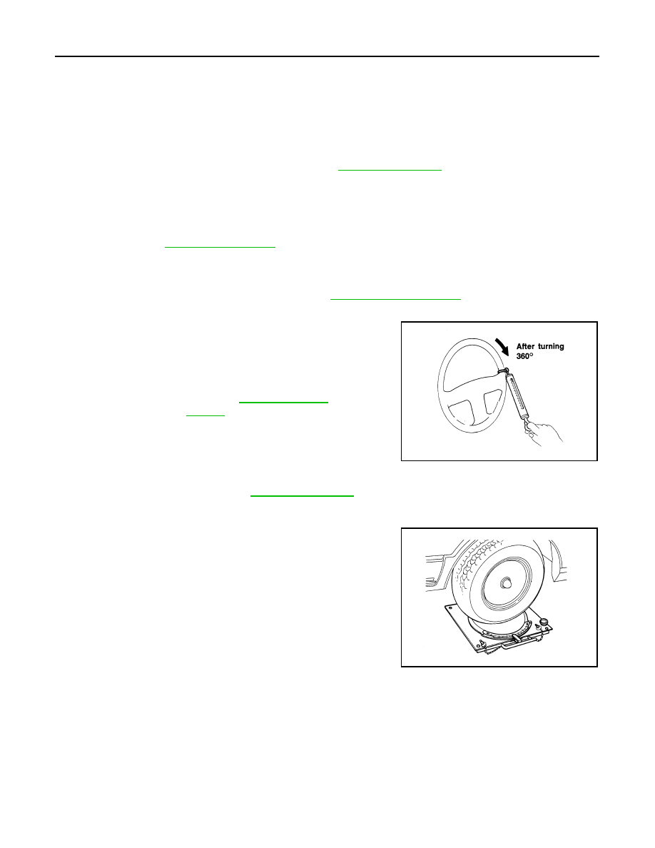
STEERING WHEEL TURNING FORCE

1. Park vehicle on a level and dry surface, set parking brake.
2. Tires need to be inflated normal pressure. Refer to 

WT-51, "Tire Air Pressure"

.

3. Set the vehicle to READY.
4. Check steering wheel turning force using Tool when steering

wheel has been turned 360

° from the neutral position.

FRONT WHEEL TURNING ANGLE

1. Perform toe-in inspection. Refer to 

FSU-11, "Inspection"

.

CAUTION:

Perform front wheel turning angle inspection, after toe-in inspection.

2. Place front wheels on turning radius gauges and rear wheels on

stands, so that vehicle can be level.

3. Check the maximum inner and outer wheel turning angles for LH

and RH road wheels.

Tool number

:  —  (J-44372)

Steering wheel 
turning force

: Refer to 

ST-47, "Steering 

Wheel"

.

WGIA0035E

FAA0016D

STEERING WHEEL

ST-17

< BASIC INSPECTION >

[WITH HEATED STEERING WHEEL]

C

D

E

F

H

I

J

K

L

M

A

B

ST

N

O

P

• Set the vehicle to READY and fully steer right and left to check

the steering angle (maximum inner wheel steering angle and

maximum outer wheel steering angle).

• Check the following items when turning angle is out of the standard.

- Check rack stroke (L).

- If rack stroke is out of specification, replace steering gear

assembly.

• Steering angles are not adjustable. Check steering gear

assembly, steering column assembly, and front suspension

components for wear or damage if any of the turning angles

are different from the specified value. Replace any of them, if

any non-standard condition exists.

A

: Inner wheel angle

B

: Outer wheel angle

Steering angle : Refer to 

ST-47, "Steering Angle"

.

SGIA0055E

Rack stroke neutral position (L) : Refer to 

ST-47, 

"Steering Gear and 
Linkage"

.

JSGIA0272ZZ

ST-18

< DTC/CIRCUIT DIAGNOSIS >

[WITH HEATED STEERING WHEEL]

HEATED STEERING WHEEL SYSTEM

DTC/CIRCUIT DIAGNOSIS

HEATED STEERING WHEEL SYSTEM

Component Function Check

INFOID:0000000010119084

1.

CHECK HEATED STEERING WHEEL SYSTEM

Check heated steering wheel system. Refer to 

ST-10, "HEATED STEERING WHEEL SYSTEM : System

Description"

.

Is the inspection result normal?

YES

>> Inspection End.

NO

>> Go to 

ST-18, "Diagnosis Procedure"

.

Diagnosis Procedure

INFOID:0000000010119085

Regarding Wiring Diagram information. Refer to 

EXL-30, "Wiring Diagram"

.

1.

CHECK POWER SOURCE

1. Turn power switch OFF.

2. Remove the heated steering wheel. Refer to 

ST-34, "Removal and Installation"

.

3. Turn power switch ON.

4. Turn heated steering wheel switch ON.

5. Check voltage between heated steering wheel harness connector terminals.

Is the inspection result normal?

YES

>> GO TO 2.

NO

>> GO TO 3.

2.

CHECK HEATED STEERING WHEEL

Check heated steering wheel. Refer to 

ST-21, "Component Inspection (Heated Steering Wheel)"

.

Is the inspection result normal?

YES

>> Inspection End.

NO

>> Replace heated steering wheel. Refer to 

ST-34, "Removal and Installation"

.

3.

CHECK GROUND CIRCUIT

Check continuity between heated steering wheel harness connector terminal and ground.

Is the inspection result normal?

YES

>> GO TO 4.

NO

>> Repair or replace damaged parts.

4.

CHECK HARNESS BETWEEN HEATED STEERING WHEEL RELAY AND HEATED STEERING WHEEL

1. Turn power switch OFF.

Heated steering wheel

Condition

Voltage (Approx.)

Connector

Terminal

M111

− 2

Within 30 seconds after 

turning ON the heated 

steering switch.

Battery voltage

Other conditions.

0 V

Heated steering wheel

Ground

Continuity

Connector

Terminal

M111

2

Yes

HEATED STEERING WHEEL SYSTEM

ST-19

< DTC/CIRCUIT DIAGNOSIS >

[WITH HEATED STEERING WHEEL]

C

D

E

F

H

I

J

K

L

M

A

B

ST

N

O

P

2. Disconnect heated steering wheel relay connector. Refer to 

ST-8, "HEATED STEERING WHEEL SYS-

TEM : Component Parts Location"

.

3. Check continuity between heated steering wheel relay harness connector terminal and heated steering

wheel harness connector terminal.

4. Check continuity between heated steering wheel relay harness connector terminal and ground.

Is the inspection result normal?

YES

>> GO TO 5.

NO

>> Repair or replace damaged parts.

5.

CHECK HEATED STEERING WHEEL RELAY

Check heated steering wheel relay. Refer to 

ST-21, "Component Inspection (Heated Steering Wheel Relay)"

.

Is the inspection result normal?

YES

>> GO TO 6.

NO

>> Replace heated steering wheel relay. Refer to 

ST-8, "HEATED STEERING WHEEL SYSTEM :

Component Parts Location"

.

6.

CHECK POWER SOURCE (BATTERY)

Check the following.

• 12V battery

• Harness for short or open between 12V battery and 15A fuse (No. 8)

• 15A fuse (No. 8)

• Harness for short or open between 15A fuse (No. 8) and heated steering wheel relay
Is the inspection result normal?

YES

>> GO TO 7.

NO

>> Repair or replace damaged parts.

7.

CHECK GROUND CIRCUIT

Check continuity between heated steering wheel switch harness connector terminal and ground.

Is the inspection result normal?

YES

>> GO TO 8.

NO

>> Repair or replace damaged parts.

8.

CHECK HARNESS BETWEEN HEATED STEERING WHEEL RELAY AND A/C AUTO AMP.

1. Check continuity between heated steering wheel relay harness connector terminal and A/C auto amp.

harness connector terminal.

2. Check continuity between heated steering wheel relay harness connector terminal and ground.

Heated steering wheel relay

Heated steering wheel

Continuity

Connector

Terminal

Connector

Terminal

M7

5

M111

1

Yes

Heated steering wheel relay

Ground

Continuity

Connector

Terminal

M7

5

No

Heated steering wheel switch

Ground

Continuity

Connector

Terminal

M6

2

Yes

Heated steering wheel relay

A/C auto amp.

Continuity

Connector

Terminal

Connector

Terminal

M7

2

M55

22

Yes


Content   ..  1129  1130  1131  1132   ..