Content .. 1073 1074 1075 1076 ..
Nissan Leaf. Manual - part 1075
SEC-62
< BASIC INSPECTION >
[WITH INTELLIGENT KEY SYSTEM]
DIAGNOSIS AND REPAIR WORK FLOW
BASIC INSPECTION
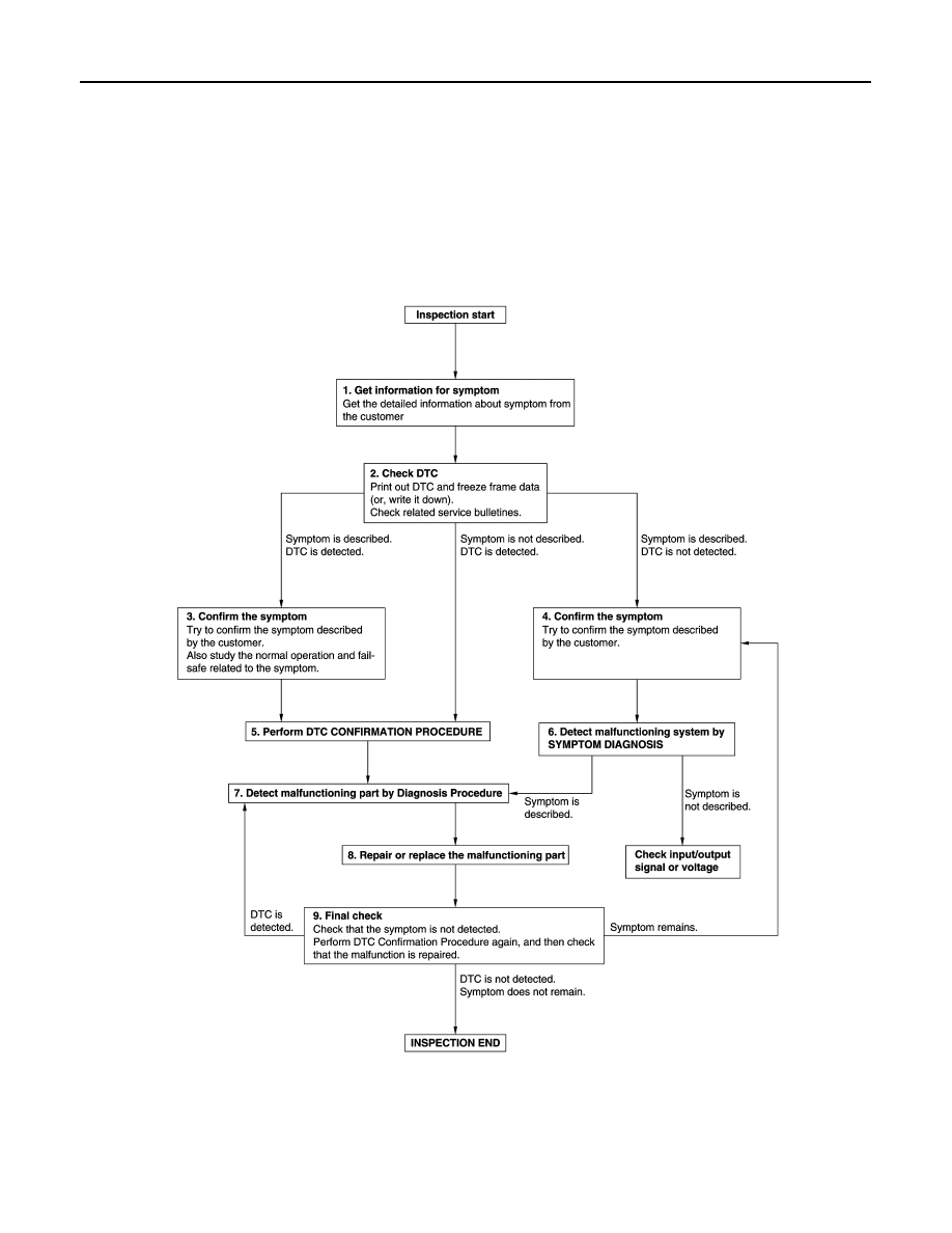
DIAGNOSIS AND REPAIR WORK FLOW
Work Flow
INFOID:0000000010119241
OVERALL SEQUENCE
DETAILED FLOW
JMKIA8652GB