Nissan Leaf. Manual - part 1042


  Index      Nissan     Nissan Leaf (2011-2014 year) - Service and Repair Manual


Search            


Content   ..  1040  1041  1042  1043   ..


Nissan Leaf. Manual - part 1042


REAR SHOCK ABSORBER

RSU-9

< REMOVAL AND INSTALLATION >

C

D

F

G

H

I

J

K

L

M

A

B

RSU

N

O

P

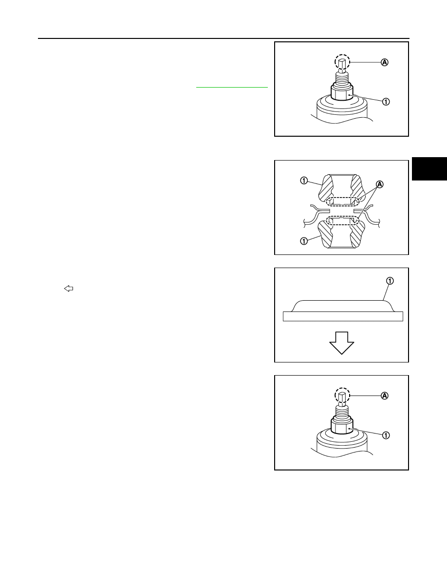
To loosen piston rod lock nut (1), fix the tip (A) of the piston rod.

7. Remove shock absorber assembly.
8. Remove bushing, distance tube, washer, bound bumper cover,

and bound bumper from shock absorber.

9. Perform inspection after removal. Refer to 

RSU-10, "Inspection"

.

INSTALLATION

Note the following, and install in the reverse order of removal.

• To install bushings (1), securely insert protrusion (A) into the hole

on the vehicle body side.

•  Install washer (1) in the direction shown.

• Perform final tightening of bolts and nuts at the shock absorber

lower side (rubber bushing), under unladen conditions with tires on

level ground.

• Hold a head (A) of shock absorber piston rod not to have it rotate,

then tighten the piston rod lock nut (1) to the specified torque.

CAUTION:

Do not reuse piston rod lock nut.

JPEIB0241ZZ

JPEIB0240ZZ

: Bushing side

JPEIB0248ZZ

JPEIB0241ZZ

RSU-10

< REMOVAL AND INSTALLATION >

REAR SHOCK ABSORBER

• When installing the cap, securely engage the cap groove (A) with

the flange on the vehicle side.

• Perform inspection after installation. Refer to 

RSU-10, "Inspec-

tion"

.

• After replacing the shock absorber, always follow the disposal pro-

cedure to discard the shock absorber. Refer to 

RSU-10, "Inspec-

tion"

.

Inspection

INFOID:0000000010119457

INSPECTION AFTER REMOVAL

Shock Absorber

Check the following items, and replace the part if necessary.

• Shock absorber for deformation, cracks, and other damage.

• Piston rod for damage, uneven wear, and distortion.

• Oil leakage

Bound Bumper, Bushing

Check for cracks and damage. Replace it if necessary.

Washer, Bound Bumper Cover, Distance Tube

• Check for cracks and damage. Replace it if necessary.

INSPECTION AFTER INSTALLATION

Check wheel alignment. Refer to 

RSU-7, "Inspection"

.

Disposal

INFOID:0000000010119458

1. Set shock absorber horizontally to the ground with the piston rod fully extracted.
2. Drill 2 – 3 mm (0.08 – 0.12 in) hole at the position ( ) from top

as shown to release gas gradually.

CAUTION:

• Wear eye protection (safety glasses).

• Wear gloves.

• Be careful with metal chips or oil blown out by the com-

pressed gas.

NOTE:

• Drill vertically in the direction show by arrow.

• Drill directly to the outer tube avoiding brackets.

• The gas is clear, colorless, odorless, and harmless.

3. Position the drilled hole downward and drain oil by moving the piston rod several times.

CAUTION:

Dispose of drained oil according to the law and local regulations.

JPEIB0244ZZ

(A)

: 20 – 30 mm (0.79 – 1.18 in)

JPEIA0161ZZ

COIL SPRING

RSU-11

< REMOVAL AND INSTALLATION >

C

D

F

G

H

I

J

K

L

M

A

B

RSU

N

O

P

COIL SPRING

Exploded View

INFOID:0000000010119459

Removal and Installation

INFOID:0000000010119460

REMOVAL

1. Remove wheel and tire using power tool. Refer to 

WT-45, "Exploded View"

.

2. Set jack under rear suspension beam.

CAUTION:

• Do not damage the suspension beam with a jack.

• Check the stable condition when using a jack.

3. Remove rear shock absorber bolts (lower side) (1). Refer to

RSU-8, "Exploded View"

.

4. Slowly lower jack, then remove upper rubber seat, coil spring

and lower rubber seat from rear suspension beam.

CAUTION:

Operate while checking that jack supporting status is sta-

ble.

5. Perform inspection after removal. Refer to 

RSU-12, "Inspection"

.

INSTALLATION

Note the following, and install in the reverse order of removal.

1.

Upper rubber seat

2.

Coil spring

3.

Lower rubber seat

4.

Rear suspension beam

JPEIB0242ZZ

JPEIB0239ZZ

RSU-12

< REMOVAL AND INSTALLATION >

COIL SPRING

• Install lower rubber seat with its protrusion (A) on the lower area

aligned with the hole of rear suspension beam.

• Securely install coil spring with the lower end of the major diameter

aligned with the steps of lower rubber seat.

• Perform inspection after installation. Refer to 

RSU-12, "Inspec-

tion"

.

Inspection

INFOID:0000000010119461

INSPECTION AFTER REMOVAL

Check lubber seat and coil spring for deformation, crack, and damage. Replace it if necessary.

INSPECTION AFTER INSTALLATION

Check wheel alignment. Refer to 

RSU-7, "Inspection"

.

(B)

: Coil spring lower end

JPEIB0272ZZ


Content   ..  1040  1041  1042  1043   ..