Nissan Leaf. Manual - part 1029


  Index      Nissan     Nissan Leaf (2011-2014 year) - Service and Repair Manual


Search            


Content   ..  1027  1028  1029  1030   ..


Nissan Leaf. Manual - part 1029


PWC-34

< DTC/CIRCUIT DIAGNOSIS >

FRONT POWER WINDOW SWITCH (PASSENGER SIDE)

FRONT POWER WINDOW SWITCH (PASSENGER SIDE)

Diagnosis Procedure

INFOID:0000000010119950

Regarding Wiring Diagram information, refer to 

PWC-16, "Wiring Diagram"

.

1.

CHECK POWER WINDOW AND DOOR LOCK/UNLOCK SWITCH INPUT SIGNAL 

1. Turn power switch OFF.

2. Disconnect power window and door lock/unlock switch RH connector.

3. Turn power switch ON.

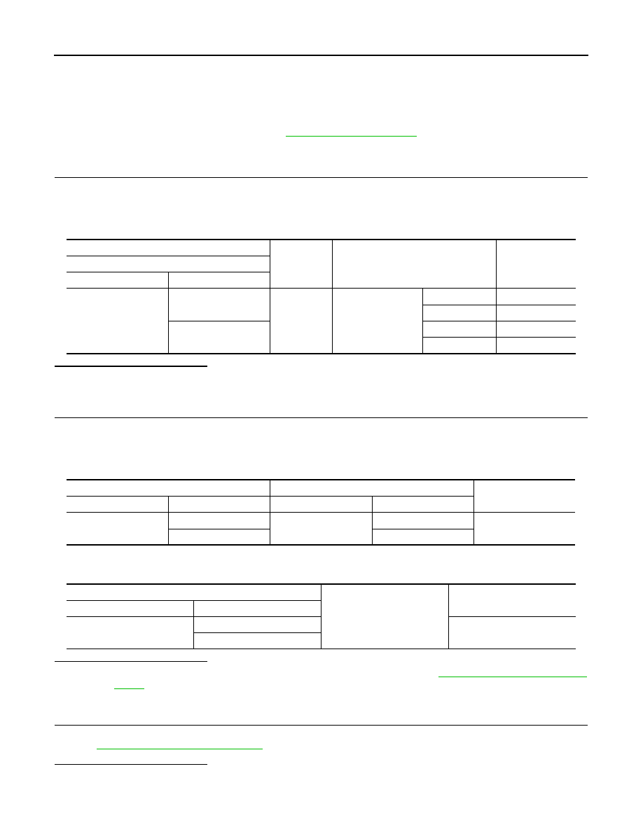
4. Check voltage between power window and door lock/unlock switch RH harness connector and ground.

Is the inspection result normal?

YES

>> GO TO 3.

NO

>> GO TO 2.

2.

CHECK POWER WINDOW AND DOOR LOCK/UNLOCK SWITCH RH CIRCUIT 

1. Turn power switch OFF.

2. Disconnect main power window and door lock/unlock switch connector.

3. Check continuity between main power window and door lock/unlock switch harness connector and power

window and door lock/unlock switch RH harness connector.

4. Check continuity between main power window and door lock/unlock switch harness connector and

ground.

Is the inspection result normal?

YES

>> Replace main power window and door lock/unlock switch. Refer to 

PWC-61, "Removal and Instal-

lation"

.

NO

>> Repair or replace harness.

3.

CHECK POWER WINDOW AND DOOR LOCK/UNLOCK SWITCH RH SWITCH

Check power window and door lock/unlock switch RH.

Refer to 

PWC-35, "Component Inspection"

.

Is the inspection result normal?

YES

>> GO TO 4.

(+)

(-)

Condition

Voltage

(Approx.)

Power window and door lock/unlock switch RH

Connector

Terminal 

D104

11

Ground

Power window and 
door lock/unlock 
switch RH

NEUTRAL

0

DOWN

Battery voltage

12

NEUTRAL

0

UP

Battery voltage

Main power window and door lock/unlock switch

Power window and door lock/unlock switch RH

Continuity

Connector

Terminal

Connector

Terminal

D35

2

D104

11

Yes

16

12

Main power window and door lock/unlock switch

Ground

Continuity

Connector

Terminal

D35

2

No

16

FRONT POWER WINDOW SWITCH (PASSENGER SIDE)

PWC-35

< DTC/CIRCUIT DIAGNOSIS >

C

D

E

F

G

H

I

J

L

M

A

B

PWC

N

O

P

NO

>> Replace power window and door lock/unlock switch RH. Refer to 

PWC-61, "Removal and Installa-

tion"

.

4.

CHECK INTERMITTENT INCIDENT

Refer to 

GI-53, "Intermittent Incident"

.

>> Inspection End.

Component Inspection

INFOID:0000000010119951

1.

CHECK POWER WINDOW AND DOOR LOCK/UNLOCK SWITCH RH

1. Turn power switch OFF.

2. Disconnect power window and door lock/unlock switch RH connector.

3. Check power window and door lock/unlock switch RH terminals under the following conditions.

Is the inspection result normal?

YES

>> Inspection End.

NO

>> Replace power window and door lock/unlock switch RH. Refer to 

PWC-61, "Removal and Installa-

tion"

.

Front power window and door lock/unlock switch RH

Condition

Continuity

Terminal

8

7

UP

Yes

11

6

11

6

NEUTRAL

12

7

8

6

DOWN

12

7

PWC-36

< DTC/CIRCUIT DIAGNOSIS >

REAR POWER WINDOW SWITCH

REAR POWER WINDOW SWITCH 

Diagnosis Procedure

INFOID:0000000010119952

Regarding Wiring Diagram information, refer to 

PWC-16, "Wiring Diagram"

.

1.

CHECK REAR POWER WINDOW SWITCH INPUT SIGNAL

1. Turn power switch OFF.

2. Disconnect rear power window switch connector.

3. Turn power switch ON.

4. Check voltage between rear power window switch harness connector and ground.

Is the inspection result normal?

YES

>> GO TO 3.

NO

>> GO TO 2.

2.

CHECK REAR POWER WINDOW SWITCH CIRCUIT

1. Turn power switch OFF.

2. Disconnect main power window and door lock/unlock switch connector.

3. Check continuity between main power window and door lock/unlock switch harness connector and rear

power window switch harness connector.

4. Check continuity between main power window and door lock/unlock switch harness connector and

ground.

Is the inspection result normal?

(+)

(-)

Condition

Voltage

(Approx.)

Rear power window switch

Connector

Terminal 

LH

D202

2

Ground

Rear power window 
switch LH

NEUTRAL

0

UP

Battery voltage 

3

NEUTRAL

DOWN

Battery voltage 

RH

D302

2

Rear power window 
switch RH

NEUTRAL

UP

Battery voltage 

3

NEUTRAL

0

DOWN

Battery voltage 

Main power window and door lock/unlock switch

Rear power window switch

Continuity

Connector

Terminal

Connector

Terminal

D35

9

LH

D202

2

Yes

8

3

7

RH

D302

2

6

3

Main power window and door lock/unlock switch

Ground

Continuity

Connector

Terminal

D35

9

No

8

7

6

REAR POWER WINDOW SWITCH

PWC-37

< DTC/CIRCUIT DIAGNOSIS >

C

D

E

F

G

H

I

J

L

M

A

B

PWC

N

O

P

YES

>> Replace main power window and door lock/unlock switch. Refer to 

PWC-61, "Removal and Instal-

lation"

.

NO

>> Repair or replace harness.

3.

CHECK REAR POWER WINDOW SWITCH

Check rear power window switch.

Refer to 

PWC-37, "Component Inspection"

.

Is the inspection result normal?

YES

>> GO TO 4.

NO

>> Replace rear power window switch. Refer to 

PWC-61, "Removal and Installation"

.

4.

CHECK INTERMITTENT INCIDENT

Refer to 

GI-53, "Intermittent Incident"

.

>> Inspection End.

Component Inspection

INFOID:0000000010119953

1.

CHECK REAR POWER WINDOW SWITCH

1. Turn power switch OFF.

2. Disconnect rear power window switch connector.

3. Check rear power window switch terminals under the following conditions.

Is the inspection result normal?

YES

>> Inspection End.

NO

>> Replace rear power window switch. Refer to 

PWC-61, "Removal and Installation"

.

Rear power window switch

Condition

Continuity

Terminal

1

5

UP

Yes

3

4

3

4

NEUTRAL

2

5

1

4

DOWN

2

5


Content   ..  1027  1028  1029  1030   ..