Nissan Primera P11. Manual - part 422


  Index      Nissan     Nissan Primera P11 (2001 year) - Service and Repair Manual


Search            


Content   ..  420  421  422  423   ..


Nissan Primera P11. Manual - part 422


CAMSHAFT VISUAL CHECK

Check camshaft for scratches, seizure and wear.
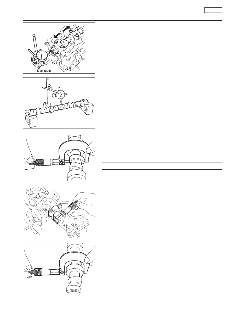
CAMSHAFT END PLAY

1.

Install camshaft in cylinder head.

2.

Tighten bracket bolts to the specified torque.

3.

Measure camshaft end play.

Camshaft end play: Standard

0.115 - 0.188 mm (0.0045 - 0.0074 in)

CAMSHAFT RUNOUT

1.

Measure camshaft runout at the center journal.

Runout (Total indicator reading):

Limit 0.05 mm (0.0020 in)

2.

If it exceeds the limit, replace camshaft.

CAMSHAFT CAM HEIGHT

1.

Measure camshaft cam height.

Cam height: Standard

Unit: mm (in)

Intake

48.70 - 48.75 (1.9173 - 1.9193)

Exhaust

49.15 - 49.20 (1.9350 - 1.9370)

2.

If wear is beyond the limit, replace camshaft.

CAMSHAFT JOURNAL CLEARANCE

Using micrometer

1.

Measure the inner diameter of camshaft bearings.

Standard inner diameter:
30.000 - 30.021 mm (1.1811 - 1.1819 in)

Tighten bracket bolts to the specified torque.

2.

Measure the outer diameter of camshaft journals.

Standard outer diameter:

29.935 - 29.955 mm (1.1785 - 1.1793 in)

If clearance exceeds the limit, replace camshaft and/or cylinder
head.

Standard clearance:

0.045 - 0.086 mm (0.0018 - 0.0034 in)

Limit: 0.1 mm (0.004 in)

SEM726B

SEM155

.

SEM730B

.

SEM727B

SEM728B

CYLINDER HEAD

CD20T

Inspection (Cont’d)

EM-147

Using plastigage

1.

Wipe off oil from camshaft journal bracket caps and brackets.

2.

Install camshaft in journal bracket caps and put plastigage on
each camshaft journal.

3.

Install cam bracket caps and tighten cam bracket cap nuts in
the correct order to the specified torque.

: 18 - 22 N·m (1.8 - 2.2 kg-m, 13 - 16 ft-lb)

4.

Remove cam bracket caps and measure maximum width of
plastigage.

Camshaft bearing clearance:

Limit

0.1 mm (0.004 in)

5.

If clearance appears to exceed the limit, replace camshaft or
cylinder head.

I

Which parts to be replaced should be decided upon after mea-
suring the diameters of the parts concerned.

Valve clearance

Checking

Check valve clearance while engine is warm and not running.
1.

Remove rocker cover.

2.

Set No. 1 cylinder at TDC on its compression stroke.

I

Align pointer with TDC mark on crankshaft pulley.

I

Check that valve lifters No.

p

1

and

p

2

are loose and valve

lifters No.

p

7

and

p

8

are tight.

If not, turn crankshaft one revolution (360°) and align as
described above.

3.

Check valve clearances of valve lifter No.

p

1

,

p

2

,

p

4

and

p

6

.

SEM879

SEM880

SEM369F

SMA406A

CYLINDER HEAD

CD20T

Inspection (Cont’d)

EM-148

I

Using a feeler gauge, measure clearance between valve lifter
and camshaft.

I

Record any valve clearance measurements which are out of
specification. They will be used later to determine the required
replacement adjusting shim.

Valve clearance for checking (Hot):

Intake

0.25 - 0.35 mm (0.010 - 0.014 in)

Exhaust

0.39 - 0.49 mm (0.015 - 0.019 in)

3.

Turn crankshaft one revolution (360°) until No. 4 cylinder is at
TDC on its compression stroke.

4.

Check valve clearances of valve lifter No.

p

3

,

p

5

,

p

7

and

p

8

.

I

Use the same procedure as mentioned in step 3.

5.

If all valve clearances are within specification, install the fol-
lowing parts:

I

Rocker cover

Adjusting

Adjust valve clearance while engine is cold.
1.

Turn crankshaft. Position cam lobe upward on camshaft for
valve that must be adjusted.

2.

Place Tool (A) around camshaft as shown in figure.

Before placing Tool (A), rotate notch toward center of cylinder
head. (See figure.) This will simplify shim removal later.
CAUTION:
Be careful not to damage cam surface with Tool (A).
3.

Rotate Tool (A) (See figure.) so that valve lifter is pushed down.

4.

Place Tool (B) between camshaft and valve lifter to retain valve
lifter.

CAUTION:

I

Tool (B) must be placed as close to camshaft bracket as
possible.

I

Be careful not to damage cam surface with Tool (B).

5.

Remove Tool (A).

SEM634F

Feeler gauge

SMA406A

.

SEM636F

Face directly upwards.

Notch

.

SEM637F

Tool (B)
KV10115120

Tool (A)
KV10115110

CYLINDER HEAD

CD20T

Checking (Cont’d)

EM-149

6.

Remove adjusting shim using a small screwdriver and a mag-
netic finger.

7.

Determine replacement adjusting shim size using the following
formula.

I

Use a micrometer to determine thickness of removed shim.

I

Calculate thickness of new adjusting shim so valve clearance
comes within specified values.
R = Thickness of removed shim
N = Thickness of new shim
M = Measured valve clearance
S = Standard valve clearance (neutral value for calculation)

Unit: mm (in)

HOT

Intake

0.30 (0.012)

Exhaust

0.44 (0.017)

COLD

Intake

0.25 (0.010)

Exhaust

0.38 (0.015)

Intake:

N = R + [M − S]

Exhaust:

N = R + [M − S]

Shims are available in 15 sizes from 2.20 mm (0.0866 in) to 2.90
mm (0.1142 in), in steps of 0.05 mm (0.0020 in).

I

Select the closest size shim to the calculated thickness.
Refer to chart in SDS, EM-198.

8.

Install new shim using a suitable tool.

I

Install with the surface on which the thickness is stamped
facing down.

9.

Place Tool (A) as explained in steps 2 and 3.

10. Remove Tool (B).
11. Remove Tool (A).
12. Recheck valve clearance.
Valve clearance:

Unit: mm (in)

For adjusting

Hot

Cold* (reference data)

Intake

0.25 - 0.35

(0.010 - 0.014)

0.20 - 0.30

(0.008 - 0.012)

Exhaust

0.39 - 0.49

(0.015 - 0.019)

0.33 - 0.43

(0.013 - 0.017)

*: At a temperature of approximately 20°C (68°F)
Whenever valve clearances are adjusted to cold specifications, check that the
clearances satisfy hot specifications and adjust again if necessary.

SEM638F

Small screwdriver

Magnetic finger

SEM145D

AEM236

Indicate
T

1

= 2.800 mm

(0.1102 in)

Shim

CYLINDER HEAD

CD20T

Adjusting (Cont’d)

EM-150


Content   ..  420  421  422  423   ..