Nissan Primera P11. Manual - part 357
 

  Index      Nissan     Nissan Primera P11 (2001 year) - Service and Repair Manual


Search            


Content   ..  355  356  357  358   ..


Nissan Primera P11. Manual - part 357


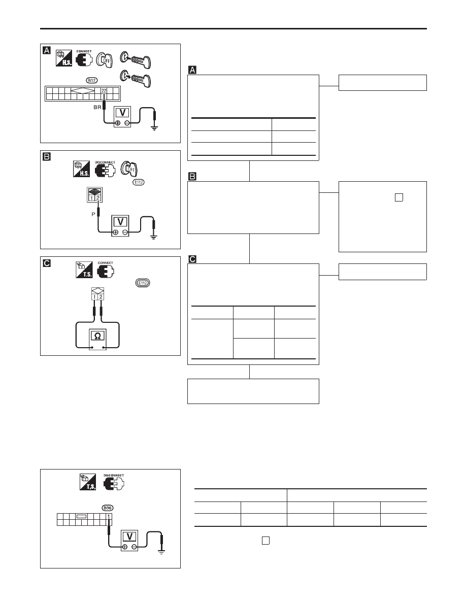
DIAGNOSTIC PROCEDURE 7
(Key switch check)

CHECK IGNITION KEY SWITCH
INPUT SIGNAL.
Check voltage between control unit ter-
minal

22

and ground.

NG

OK

Key switch is OK.

CHECK KEY SWITCH POWER SUP-
PLY.
Check voltage between key switch har-
ness terminal

2

and ground.

Battery voltage should exist.

OK

NG

Check the following.

10A fuse [No. 16 ,
located in fuse block
(J/B)]

Harness for open or
short between key
switch and fuse

CHECK KEY SWITCH.
1) Disconnect key switch connector.
2) Check continuity between key

switch terminals.

OK

NG

Replace key switch.

Check harness for open or short
between control unit and key switch.

Condition of key switch

Voltage [V]

Key is inserted

Approx. 12

Key withdrawn

0

Terminals

Condition

Continuity

1

-

2

Key is

inserted.

Yes

Key is with-

drawn.

No

DIAGNOSTIC PROCEDURE 8
(Ignition switch “ON” circuit check)

Terminals

Ignition switch position

OFF

ACC

ON

1

Ground

0V

0V

Battery voltage

If NG, check the following.

10A fuse [No.

26

, located in the fuse block (J/B)]

Harness for open or short

YEL453B

Time control unit
connector

YEL826

Key switch connector

YEL827

Key switch connector

YEL454B

Time control
unit connector

POWER DOOR LOCK — Super Lock —

Trouble Diagnoses (Cont’d)

EL-295

System Description

The multi-remote control system controls operation of the

power door lock (and super lock)

OPERATED PROCEDURE

Power door lock operation

When the following input signals are both supplied:

Key switch OFF (when ignition key is not inserted in key cylinder);

door switch CLOSED (when all the doors are closed);

The two above signals are already input into time control unit. At this point, time control unit receives a LOCK
signal from remote controller. Time control unit locks all doors and set super lock with input of LOCK signal
from remote controller.
When an UNLOCK signal is sent from remote controller once, driver’s door will be unlocked and release
super lock.
Then, if an UNLOCK signal is sent from remote controller again, all other door will be unlocked.

Multi-remote controller ID code entry

For detailed procedure, refer to “ID Code Entry Procedure” in EL-305.

MULTI-REMOTE CONTROL SYSTEM

EL-296

Schematic

YEL206C

IGNITION SWITCH

On or START

BATTERY

BATTERY

(Via fusible link)

FUSE

FUSE

FUSIBLE
LINK

TIME CONTROL UNIT

To door lock
actuators

DOOR LOCK
ACTUATOR
ASSEMBLY
(DRIVER’S SIDE)

DOOR LOCK
ACTUATOR
ASSEMBLY
(REAR LH)

UNLOCK
SENSOR

UNLOCK
SENSOR

DOOR LOCK
ACTUATOR
ASSEMBLY
(REAR RH)

DOOR LOCK
ACTUATOR
ASSEMBLY
(PASSENGER SIDE)

UNLOCK
SENSOR

UNLOCK
SENSOR

TRUNK OR
LUGGAGE
ROOM
LAMP SWITCH

FRONT
DOOR
SWITCH
(DRIVER’S
SIDE)

FRONT
DOOR
SWITCH
(PASSENGER
SIDE)

REAR
DOOR
SWITCH
LH

REAR
DOOR
SWITCH
RH

UNLOCK

UNLOCK

UNLOCK

UNLOCK

KEY
SWITCH

CIRCUIT
BREAKER-1

LOCK

LOCK

LOCK

LOCK

MULTI-REMOTE CONTROL SYSTEM

EL-297

Wiring Diagram — MULTI —

YEL207C

IGNITION SWITCH

ON or START

BATTERY

CIRCUIT
BREAKER-1

FUSE
BLOCK
(J/B)

Refer to EL-POWER

TIME
CONTROL
UNIT

KEY
SWITCH

INSERTED

WITHDRAWN

REFER TO THE FOLLOWING

FUSE BLOCK - Junction Box (J/B)

FUSE BLOCK - Junction Box (J/B)

FUSE BLOCK - Junction Box (J/B)

: This connector is not shown in “HARNESS LAYOUT” of EL section.

MULTI-REMOTE CONTROL SYSTEM

EL-298


Content   ..  355  356  357  358   ..