Nissan Primera P11. Manual - part 354
 

  Index      Nissan     Nissan Primera P11 (2001 year) - Service and Repair Manual


Search            


Content   ..  352  353  354  355   ..


Nissan Primera P11. Manual - part 354


Trouble Diagnoses

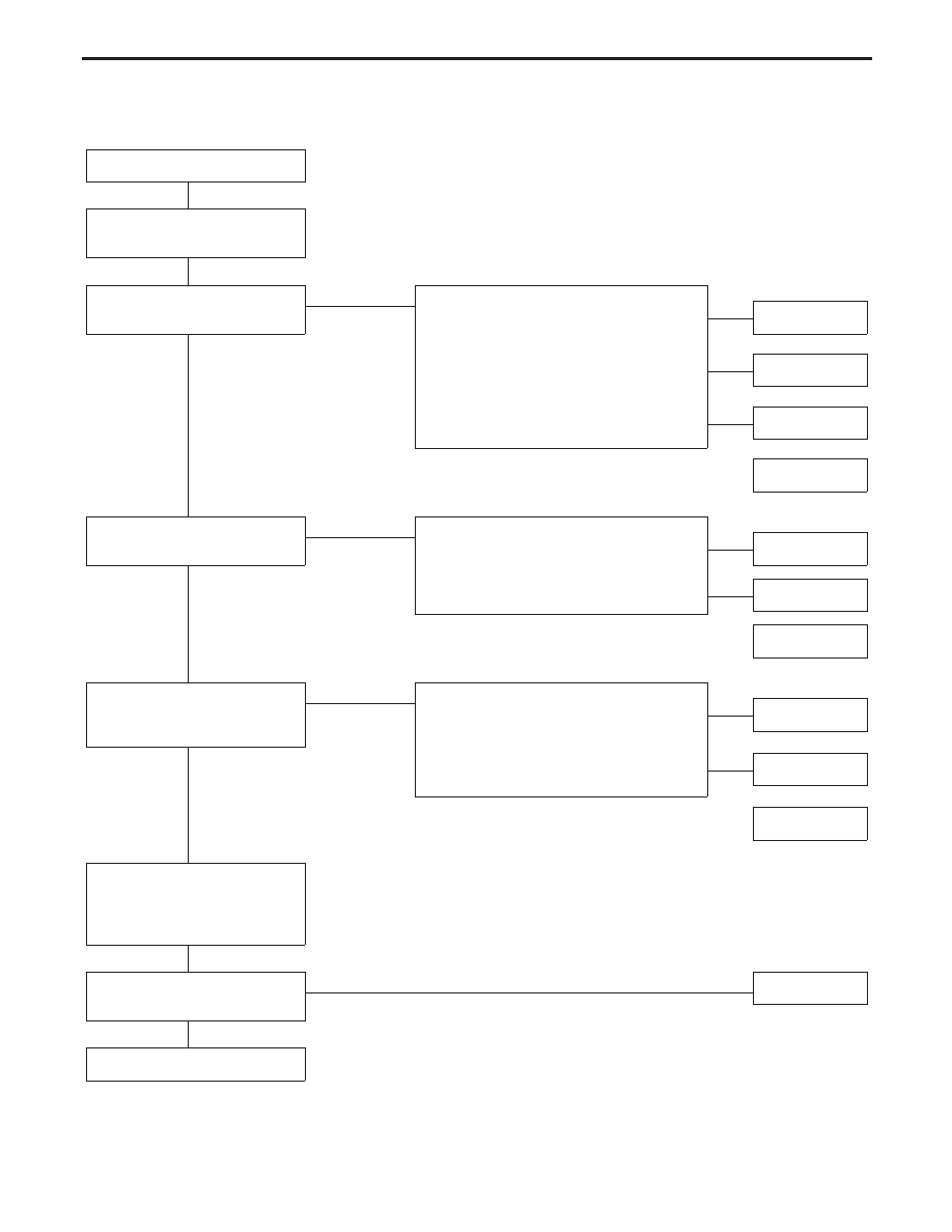
PRELIMINARY CHECK

CHECK-IN

Open all windows and remove

key from ignition key cylinder.

Does power door lock operate

properly?

Yes

왘

No (All doors)

Power door lock does not operate by using;

— any switch.

......................................................................

— driver side lock knob switch and/or key

cylinder.

......................................................................

— passenger side lock knob switch and/or

key cylinder.

★

왘

SYMPTOM 1

왘

SYMPTOM 2

왘

SYMPTOM 3

No (Specific door)

SYMPTOM 4

Does super lock set by using

door key cylinder?

Yes

왘

No (All doors)

Super lock does not set by using;

— both door key cylinders.

......................................................................

— one of door key cylinders.

왘

SYMPTOM 5

왘

SYMPTOM 6

No (Specific door)

SYMPTOM 9

Does super lock release by

using door key cylinder or IGN

key switch?

Yes

왘

No All doors

Super lock does not release by using;

— one or both door key cylinders.

......................................................................

— IGN key switch.

(Signal from NATS IMMU)

왘

SYMPTOM 7

왘

SYMPTOM 8

No (Specific door)

SYMPTOM 9

Insert key to ignition key

cylinder, open any door and

lock the door using driver side

knob lock switch.

Does key reminder system

operate properly?

Yes

왘

No

SYMPTOM 10

INSPECTION END

After performing preliminary check, go to symptom chart on the next page.

★

When one or more doors are opened, with lock knob on passenger door setting to LOCK, will lock pas-
senger door only. (Power door lock system will not operate.)

왔

왔

왔

왔

왔

왔

왔

POWER DOOR LOCK — Super Lock —

EL-283

Before starting trouble diagnoses below, perform preliminary check, EL-283.
Symptom numbers in the symptom chart correspond with those of Preliminary check.

SYMPTOM CHART

REFERENCE PAGE

EL-285

EL-286

EL-287

EL-288,

289

EL-290,

291

EL-292,

293

EL-294

EL-295

EL-295

SYMPTOM

Power

supply

and

ground

circuit

check

Procedure

1

(Door

unlock

sensor

check)

Procedure

2

(Door

key

cylinder

switch

check)

Procedure

3

(Door

lock

actuator

check)

Procedure

4

(Super

lock

actuator

check)

Procedure

5

(Door

switch

check)

Procedure

6

(NA

TS

release

signal

check)

Procedure

7

(Key

switch

check)

Procedure

8

(Ignition

switch

“ON

”

circuit

check)

1

Power door lock does not operate
using any switch.

X

X

X

2

Power door lock does not operate
with any switch of driver side.

X

3

Power door lock does not operate
with any switch of passenger side.

X

X

4

Specific door lock acutator does
not operate.

X

5

Super lock cannot be set by both
door key cylinders.

X

X

X

X

X

6

Super lock cannot be set by one of
door key cylinders.

X

7

*Super lock cannot be released by
one or both door key cylinders.

X

8

*Super lock cannot be released by
ignition key switch. (Signal from
NATS IMMU)

X

9

Specific super lock actuator does
not operate.

X

10

*Key reminder system does not
operate.

X

X

X: Applicable
*: Make sure the power door lock and key reminder system operate properly.

POWER DOOR LOCK — Super Lock —

Trouble Diagnoses (Cont’d)

EL-284

POWER SUPPLY AND GROUND CIRCUIT CHECK

Main power supply circuit check

Terminals

Ignition switch position

䊝

䊞

LOCK

ACC

ON

쑗

9

Ground

Battery
voltage

Battery
voltage

Battery
voltage

Ground circuit check

Terminals

Continuity

쑗

16

- Ground

Yes

Time control
unit connector

YEL445B

YEL431B

Time control unit connector

POWER DOOR LOCK — Super Lock —

Trouble Diagnoses (Cont’d)

EL-285

DIAGNOSTIC PROCEDURE 1
(Door unlock sensor check)

CHECK DOOR UNLOCK SENSOR
INPUT SIGNAL.
Check voltage between time control
unit connector terminals

쑗

35

or

쑗

36

and ground.

NG

왘

OK

Door unlock sensor is
OK.

CHECK DOOR UNLOCK SENSOR.
1) Disconnect door unlock sensor con-

nector.

2) Check continuity between door

unlock sensor terminals.

OK

왘

NG

Replace door lock actua-
tor assembly.

Check the following:

●

Door unlock sensor ground circuit.

●

Harness for open or short-circuit
between control unit and door unlock
sensor

Terminals

Condition

Voltage

[V]

䊝

䊞

Driver
side

쑗

35

Ground

Locked

Approx.

2

(Approx.

20 sec.)

Unlocked

0

Pas-
sen-
ger
side

쑗

36

Ground

Locked

Approx.

12

(Approx.

20 sec.)

Unlocked

0

Terminals

Condition

Continuity

쑗

2

-

쑗

5

Locked

No

Unlocked

Yes

YEL446B

Time control unit connector

YEL815

Door lock actuator assem-
bly connectors

Driver side

:

Passenger side:

왔

왔

POWER DOOR LOCK — Super Lock —

Trouble Diagnoses (Cont’d)

EL-286


Content   ..  352  353  354  355   ..