Nissan Primera P11. Manual - part 208
Fuel Pressure Release
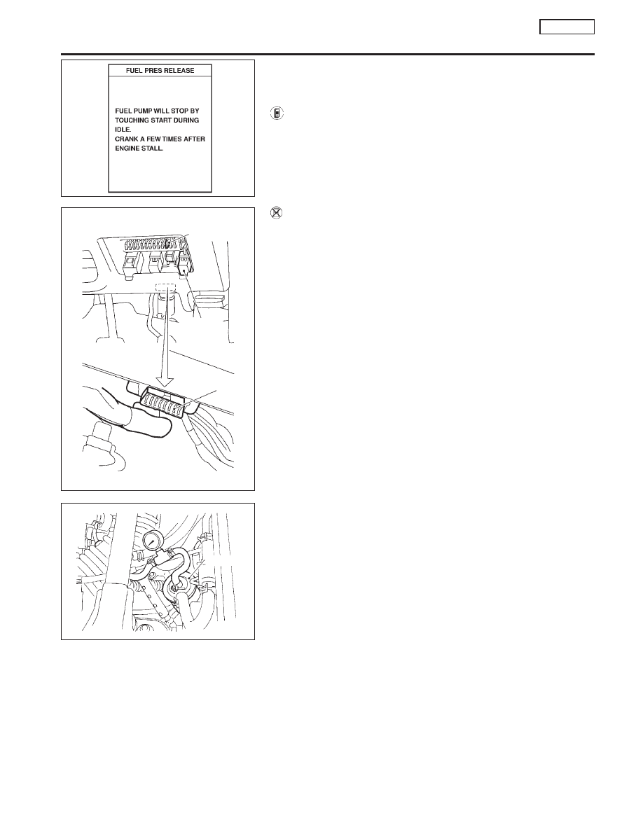
NCEC0024
Before disconnecting fuel line, release fuel pressure from fuel
line to eliminate danger.
WITH CONSULT-II
NCEC0024S01
1.
Start engine.
2.
Perform “FUEL PRES RELEASE” in “WORK SUPPORT”
mode with CONSULT-II.
3.
After engine stalls, crank it two or three times to release all fuel
pressure.
4.
Turn ignition switch OFF.
WITHOUT CONSULT-II
NCEC0024S02
1.
Remove fuse for fuel pump. Refer to fuse block cover for fuse
location.
2.
Start engine.
3.
After engine stalls, crank it two or three times to release all fuel
pressure.
4.
Turn ignition switch OFF and reconnect fuel pump fuse.
Fuel Pressure Check
NCEC0025
I
When reconnecting fuel line, always use new clamps.
I
Make sure that clamp screw does not contact adjacent
parts.
I
Use a torque driver to tighten clamps.
I
Use Pressure Gauge to check fuel pressure.
I
Do not perform fuel pressure check with system operat-
ing. Fuel pressure gauge may indicate false readings.
1.
Release fuel pressure to zero.
2.
Disconnect fuel hose between fuel filter and fuel tube (engine
side).
3.
Install pressure gauge between fuel filter and fuel tube.
4.
Start engine and check for fuel leakage.
5.
Read the indication of fuel pressure gauge.
At idle speed:
With vacuum hose connected
Approximately 235 kPa (2.35 bar, 2.4 kg/cm
2
, 34
psi)
With vacuum hose disconnected
Approximately 294 kPa (2.94 bar, 3.0 kg/cm
2
, 43
psi)
PEF823K
Fuel pump fuse
Fuel pump
relay
Data link connector
SEF192X
Fuel filter
SEF194X
BASIC SERVICE PROCEDURE
SR20DE
Fuel Pressure Release
EC-31