Nissan Primera P11. Manual - part 120


  Index      Nissan     Nissan Primera P11 (2001 year) - Service and Repair Manual


Search            


Content   ..  118  119  120  121   ..


Nissan Primera P11. Manual - part 120


Emission-related Diagnostic Information

NCEC0031

DTC AND 1ST TRIP DTC

NCEC0031S01

The 1st trip DTC (whose number is the same as the DTC number) is displayed for the latest self-diagnostic
result obtained. If the ECM memory was cleared previously, and the 1st trip DTC did not reoccur, the 1st trip
DTC will not be displayed. If a malfunction is detected during the 1st trip, the 1st trip DTC is stored in the ECM
memory. The MI will not light up (two trip detection logic). If the same malfunction is not detected in the 2nd
trip (meeting the required driving pattern), the 1st trip DTC is cleared from the ECM memory. If the same mal-
function is detected in the 2nd trip, both the 1st trip DTC and DTC are stored in the ECM memory and the MI
lights up. In other words, the DTC is stored in the ECM memory and the MI lights up when the same malfunc-
tion occurs in two consecutive trips. If a 1st trip DTC is stored and a non-diagnostic operation is performed
between the 1st and 2nd trips, only the 1st trip DTC will continue to be stored. For malfunctions that blink or
light up the MI during the 1st trip, the DTC and 1st trip DTC are stored in the ECM memory.
Procedures for clearing the DTC and the 1st trip DTC from the ECM memory are described in “HOW TO
ERASE EMISSION-RELATED DIAGNOSTIC INFORMATION”. Refer to EC-QG-44.
For malfunctions in which 1st trip DTCs are displayed, refer to EC-QG-42. These items are required by legal
regulations to continuously monitor the system/component. In addition, the items monitored non-continuously
are also displayed on CONSULT-II.
1st trip DTC is specified in Mode 7 of ISO15031-5. 1st trip DTC detection occurs without lighting up the MI
and therefore does not warn the driver of a problem. However, 1st trip DTC detection will not prevent the
vehicle from being tested, for example during Inspection/Maintenance (I/M) tests.
When a 1st trip DTC is detected, check, print out or write down and erase (1st trip) DTC and Freeze Frame
data as specified in “Work Flow” procedure Step II, refer to page EC-QG-70. Then perform “DTC Confirma-
tion Procedure” or “Overall Function Check” to try to duplicate the problem. If the malfunction is duplicated,
the item requires repair.

How to read DTC and 1st Trip DTC

NCEC0031S0101

DTC and 1st trip DTC can be read by the following methods.
1)

No Tools

The number of blinks of MI in the Diagnostic Test Mode II (Self-Diagnostic Results) Examples: 0340, 1320,
0705, 0750, etc.
These DTCs are controlled by NISSAN.

2)

With CONSULT-II

With GST

CONSULT-II or GST (Generic Scan Tool) Examples: P0340, P1320, P0705, P0750, etc.
These DTCs are prescribed by ISO15031-6.
(CONSULT-II also displays the malfunctioning component or system.)

I

1st trip DTC No. is the same as DTC No.

I

Output of a DTC indicates a malfunction. However, Mode II and GST do not indicate whether the
malfunction is still occurring or has occurred in the past and has returned to normal.
CONSULT-II can identify malfunction status as shown below. Therefore, using CONSULT-II (if avail-
able) is recommended.

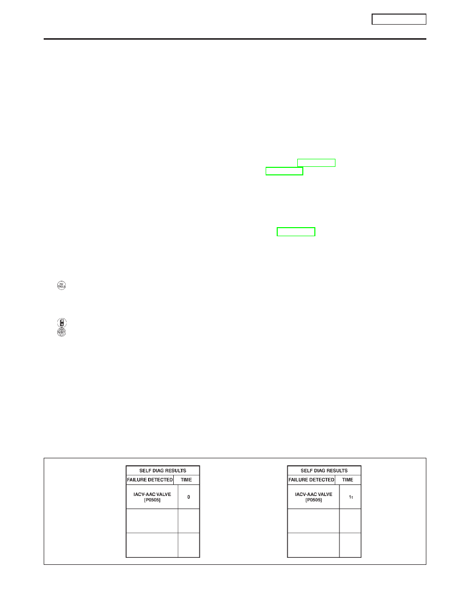
A sample of CONSULT-II display for DTC is shown below. DTC or 1st trip DTC of a malfunction is displayed
in SELF-DIAGNOSTIC RESULTS mode of CONSULT-II. Time data indicates how many times the vehicle was
driven after the last detection of a DTC.
If the DTC is being detected currently, the time data will be “0”.
If a 1st trip DTC is stored in the ECM, the time data will be “[1t]”.

NEF065A

DTC
display

1st trip
DTC
display

ON BOARD DIAGNOSTIC SYSTEM DESCRIPTION

QG16

I

18DE

Emission-related Diagnostic Information

EC-37

FREEZE FRAME DATA AND 1ST TRIP FREEZE FRAME DATA

NCEC0031S02

The ECM records the driving conditions such as fuel system status, calculated load value, engine coolant
temperature, short term fuel trim, long term fuel trim, engine speed, vehicle speed and absolute pressure
sensor at the moment a malfunction is detected.
Data which are stored in the ECM memory, along with the 1st trip DTC, are called 1st trip freeze frame data.
The data, stored together with the DTC data, are called freeze frame data and displayed on CONSULT-II or
GST. The 1st trip freeze frame data can only be displayed on the CONSULT-II screen, not on the GST. For
details, see EC-QG-58.
Only one set of freeze frame data (either 1st trip freeze frame data or freeze frame data) can be stored in the
ECM. 1st trip freeze frame data is stored in the ECM memory along with the 1st trip DTC. There is no prior-
ity for 1st trip freeze frame data and it is updated each time a different 1st trip DTC is detected. However, once
freeze frame data (2nd trip detection/MI on) is stored in the ECM memory, 1st trip freeze frame data is no
longer stored. Remember, only one set of freeze frame data can be stored in the ECM. The ECM has the fol-
lowing priorities to update the data.

Priority

Items

1

Freeze frame data

Misfire — DTC: P0300 - P0304 (0300 - 0304)
Fuel Injection System Function — DTC: P0171 (0171), P0172 (0172)

2

Except the above items

3

1st trip freeze frame data

For example, the EGR malfunction (Priority: 2) was detected and the freeze frame data was stored in the 2nd
trip. After that when the misfire (Priority: 1) is detected in another trip, the freeze frame data will be updated
from the EGR malfunction to the misfire. The 1st trip freeze frame data is updated each time a different mal-
function is detected. There is no priority for 1st trip freeze frame data. However, once freeze frame data is
stored in the ECM memory, 1st trip freeze data is no longer stored (because only one freeze frame data or
1st trip freeze frame data can be stored in the ECM). If freeze frame data is stored in the ECM memory and
freeze frame data with the same priority occurs later, the first (original) freeze frame data remains unchanged
in the ECM memory.
Both 1st trip freeze frame data and freeze frame data (along with the DTCs) are cleared when the ECM
memory is erased. Procedures for clearing the ECM memory are described in “HOW TO ERASE EMISSION-
RELATED DIAGNOSTIC INFORMATION”. Refer to EC-QG-44.

SYSTEM READINESS TEST (SRT) CODE

NCEC0031S03

System Readiness Test (SRT) code is specified in Mode 1 of ISO15031-5. It indicates whether the self-diag-
nostic tests for non-continuously monitored items have been completed or not.
Inspection/Maintenance (I/M) tests of the on board diagnostic (OBD) II system may become the legal require-
ments in some states/areas. All SRT codes must be set in this case. Unless all SRT codes are set, conduct-
ing the I/M test may not be allowed.
SRT codes are set after self-diagnosis has been performed one or more times. This occurs regardless of
whether the diagnosis is in “OK” or “NG”, and whether or not the diagnosis is performed in consecutive trips.
The following table lists the four SRT items (14 test items) for the ECM used in P11 models.

SRT items

Self-diagnostic test items

Catalyst monitoring

I

Three way catalyst function P0420 (0420)

Oxygen sensor monitoring

I

Heated oxygen sensor 1 (front) (Circuit) P0130 (0130)

I

Heated oxygen sensor 1 (front) (Lean shift monitoring) P0131 (0131)

I

Heated oxygen sensor 1 (front) (Rich shift monitoring) P0132 (0132)

I

Heated oxygen sensor 1 (front) (Response monitoring) P0133 (0133)

I

Heated oxygen sensor 1 (front) (High voltage) P0134 (0134)

I

Heated oxygen sensor 2 (rear) (Min. voltage monitoring) P0137 (0137)

I

Heated oxygen sensor 2 (rear) (Max. voltage monitoring) P0138 (0138)

I

Heated oxygen sensor 2 (rear) (Response monitoring) P0139 (0139)

I

Heated oxygen sensor 2 (rear) (High voltage) P0140 (0140)

Oxygen sensor heater monitoring

I

Heated oxygen sensor 1 (front) heater P0135 (0135)

I

Heated oxygen sensor 2 (rear) heater P0141 (0141)

EGR system monitoring
(If so equipped)

I

EGR function (Close) P0400 (0400)

I

EGR function (Open) P1402 (1402)

ON BOARD DIAGNOSTIC SYSTEM DESCRIPTION

QG16

I

18DE

Emission-related Diagnostic Information (Cont’d)

EC-38

Together with the DTC, the SRT code is cleared from the ECM memory using the method described later
(Refer to EC-QG-44). In addition, after engine control components/system are repaired or if the battery termi-
nals remain disconnected for more than 24 hours, all SRT codes may be cleared from the ECM memory.

How to Display SRT Code

NCEC0031S0301

1.

With CONSULT-II

Selecting “SRT STATUS” in “DTC CONFIRMATION” mode with CONSULT-II.
For items whose SRT codes are set, a “CMPLT” is displayed on the CONSULT-II screen; for items whose
SRT codes are not set, “INCMP” is displayed as shown below.

2.

With GST

Selecting Mode 1 with GST (Generic Scan Tool)

How to Set SRT Code

NCEC0031S0302

To set all SRT codes, self-diagnosis for the items indicated above must be performed one or more times. Each
diagnosis may require a long period of actual driving under various conditions. The most efficient driving pat-
tern in which SRT codes can be properly set is explained on the next page. The driving pattern should be
performed one or more times to set all SRT codes.

SEF821Y

ON BOARD DIAGNOSTIC SYSTEM DESCRIPTION

QG16

I

18DE

Emission-related Diagnostic Information (Cont’d)

EC-39

Driving Pattern

NCEC0031S0303

YEC130A

ON BOARD DIAGNOSTIC SYSTEM DESCRIPTION

QG16

I

18DE

Emission-related Diagnostic Information (Cont’d)

EC-40


Content   ..  118  119  120  121   ..