Nissan Frontier D22. Manual - part 919
SRS-42
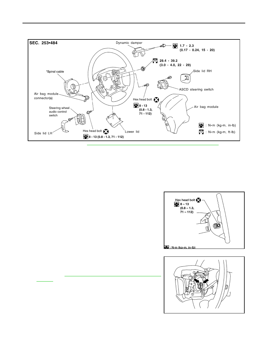
DRIVER AIR BAG MODULE AND SPIRAL CABLE
DRIVER AIR BAG MODULE AND SPIRAL CABLE
PFP:K8510
Removal and Installation
EHS000T8
*If equipped with VDC, refer to
BRC-55, "Adjustment of Steering Angle Sensor Neutral Position"
for steering
wheel angle sensor adjustment.
Removal
EHS000T9
CAUTION:
●
Before servicing SRS, turn the ignition switch OFF, disconnect both battery cables and wait at
least 3 minutes.
●
Always work from the side of an air bag module.
1.
Remove side lids and/or switch covers and switches.
2.
Remove the right and left special hex head bolts.
3.
Disconnect the air bag harness connectors, and remove the air
bag module.
●
For removal/installation of the direct-connect SRS connec-
tors, refer to
SRS-8, "Direct-connect SRS Component Con-
LHIA0021E
WRS235
WHIA0011E