Nissan Frontier D22. Manual - part 862
PS-8
ON-VEHICLE SERVICE
Checking Fluid Leakage
EGS000L4
Check lines for improper attachment, leaks, cracks, damage, chafing
and deterioration.
1.
Run engine between idle speed and 1,000 rpm.
2.
Bring power steering fluid up to adequate operating tempera-
ture. [Make sure temperature of fluid is approximately 60 to
80
°C (140 to 176°F).]
3.
Turn steering wheel right-to-left several times.
4.
Hold steering wheel at each “lock” position for 5 seconds and
carefully check for fluid leakage.
CAUTION:
Do not hold steering wheel at lock position for more than 15
seconds.
5.
If fluid leakage from any line is noticed, loosen flare nut and then retighten.
CAUTION:
Do not overtighten connector as this can damage O-ring, washer and connector.
6.
If fluid leakage from power steering pump is noticed, check power steering oil pump. Refer to
7.
If fluid leakage from power steering gear is noticed, check power steering gear. Refer to
.
Bleeding Hydraulic System
EGS000L5
1.
Raise front end of vehicle until wheels are clear of the ground.
2.
Add fluid to reservoir tank to specified level. Quickly turn steer-
ing wheel fully to right and left and lightly touch steering stop-
pers.
Repeat steering wheel operation until fluid level no longer
decreases.
3.
Start engine.
Repeat step 2 above.
●
Incomplete air bleeding will cause the following to occur:
–
Air bubbles in reservoir tank
–
Clicking noise in power steering pump
–
Excessive buzzing in power steering pump
When this happens, bleed air again.
Fluid noise may occur in the valve or power steering pump. This is common when the vehicle is stationary or
while turning the steering wheel slowly. This does not affect the performance or durability of the system.
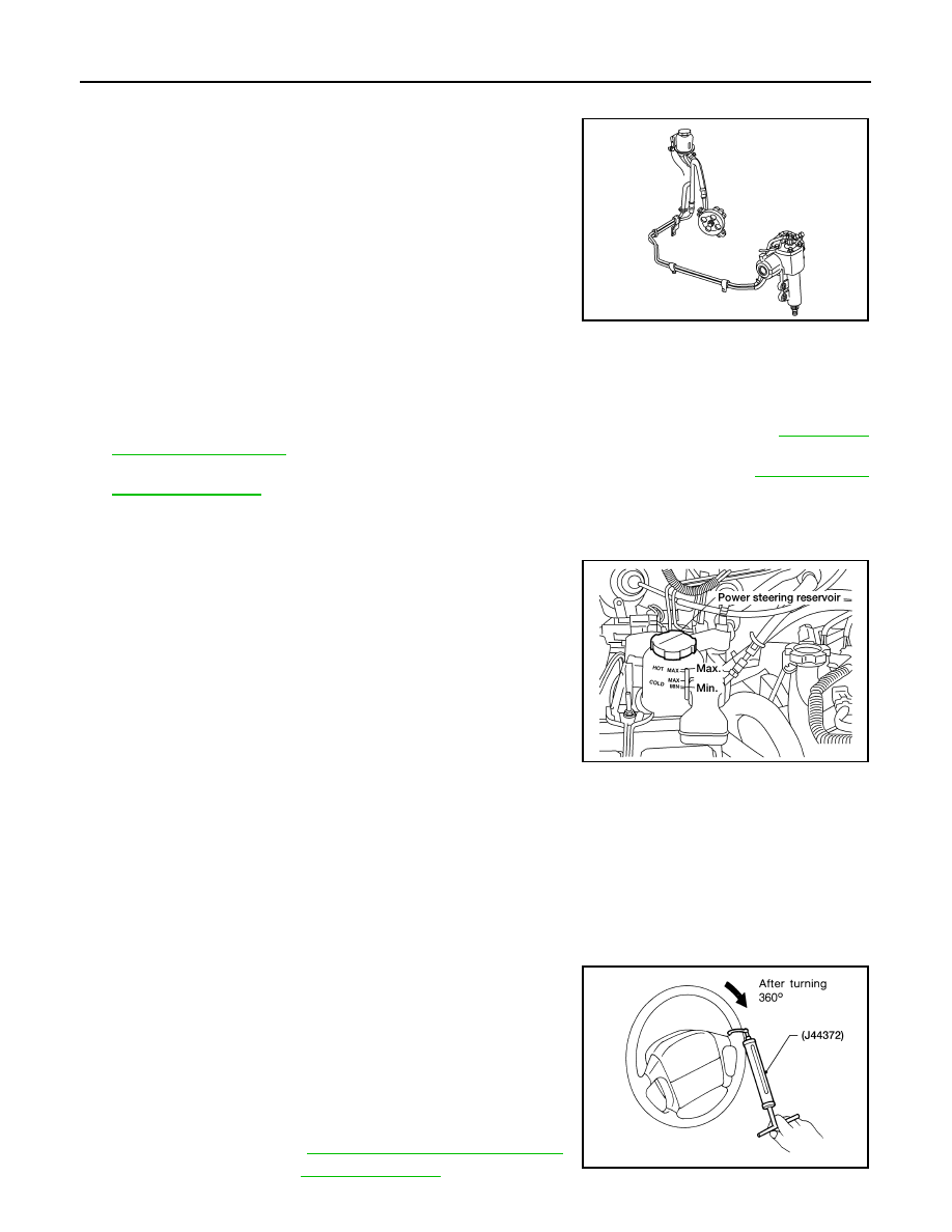
Checking Steering Wheel Turning Force
EGS000L6
1.
Park vehicle on a level, dry surface and set parking brake.
2.
Start engine and run at idle speed or 1,000 rpm.
3.
Bring power steering fluid up to adequate operating temperature. [Make sure temperature of fluid is
approximately 60 to 80
°C (140 to 176°F).]
4.
Check steering wheel turning force when steering wheel has
been turned 360
° from neutral position.
NOTE:
Tires need to be inflated to normal pressure.
5.
If steering wheel turning force is out of specification, check the
following:
a.
Hydraulic system. Refer to
PS-9, "Checking Hydraulic System"
.
b.
Steering column. Refer to
AST255
AST253
Steering wheel turning
force
: 39 N (4 kg, 9 lb) or less
WST049