Nissan Frontier D22. Manual - part 730
FUEL TANK
FL-3
C
D
E
F
G
H
I
J
K
L
M
A
FL
FUEL TANK
PFP:17202
Removal and Installation
EBS00HZG
WARNING:
When replacing fuel line parts, be sure to observe the following:
●
Put a “CAUTION: INFLAMMABLE” sign in workshop.
●
Do not smoke while servicing fuel system. Keep open flames and sparks away from work area.
●
Be sure to furnish the workshop with a CO
2
fire extinguisher.
CAUTION:
●
Before removing fuel line parts, carry out the following procedures:
–
Put drained fuel in an explosion-proof container and put lid on securely.
–
Release fuel pressure from fuel line. Refer to
EC-46, "FUEL PRESSURE RELEASE"
(KA24DE),
EC-1218, "FUEL PRESSURE RELEASE"
(VG33ER).
–
Disconnect battery ground cable.
●
Remove quick connectors with commercial service tool.
●
Always replace O-ring with a new one.
●
Do not kink or twist hoses and tubes when installed.
●
Do not tighten hose clamps excessively to avoid damaging hoses.
●
Perform an inspection and installation of EVAP system parts as necessary. Refer to
(KA24DE),
EC-1164, "EVAPORATIVE EMISSION SYSTEM"
(VG33E),
EC-1740, "EVAPORATIVE EMISSION SYSTEM"
(VG33ER).
●
For inspection and installation of ORVR system parts, refer to
(KA24DE),
EC-1172, "ON BOARD REFUELING VAPOR RECOVERY
EC-1748, "ON BOARD REFUELING VAPOR RECOVERY (ORVR)"
(VG33ER).
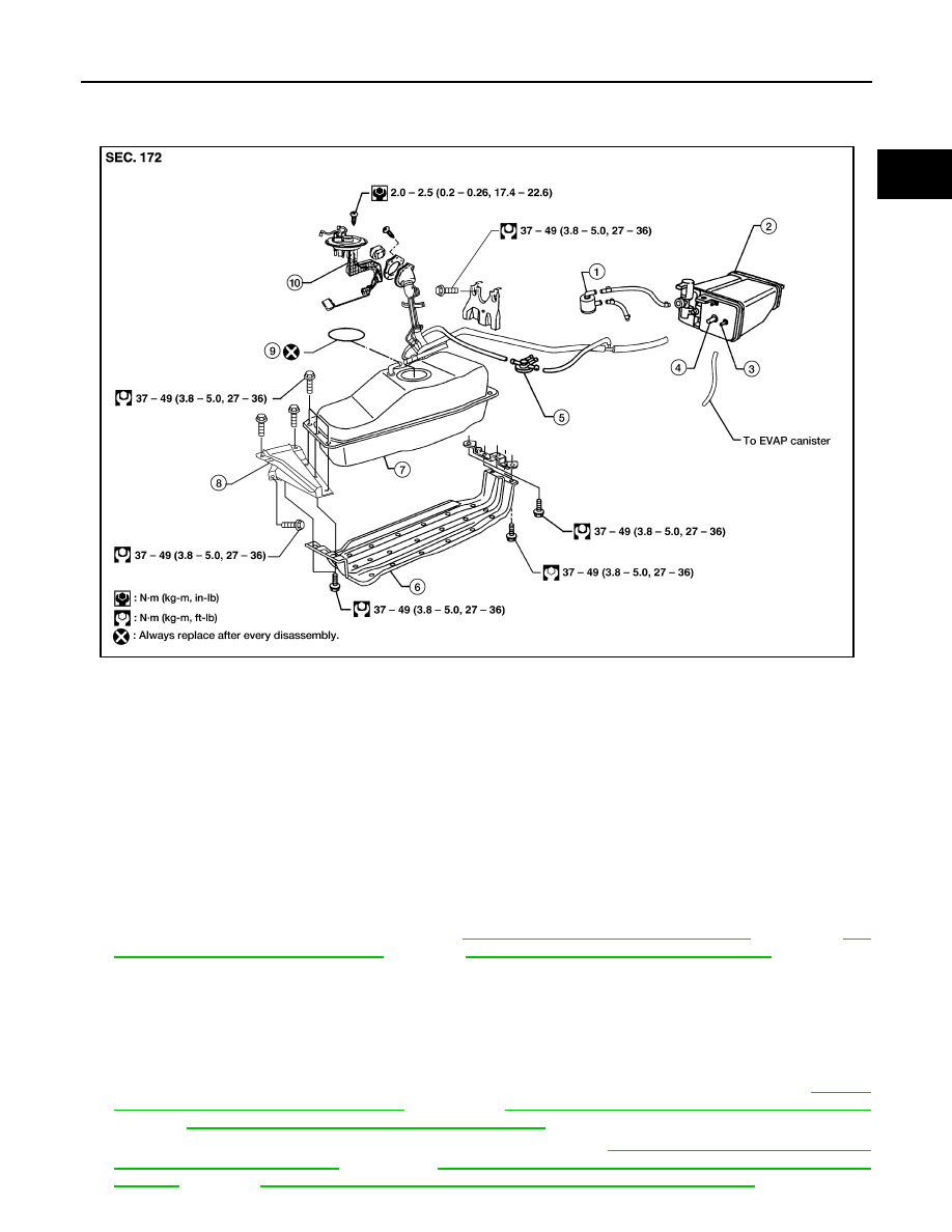
1.
Water separator
2.
EVAP canister
3.
Purge
4.
Charge
5.
Vacuum cut valve
6.
Fuel tank protector
7.
Fuel tank assembly
8.
Fuel tank bracket
9.
O-ring
10. Fuel level sensor
LBIA0331E