Nissan Frontier D22. Manual - part 645
 

  Index      Nissan     Nissan Frontier D22 Pickup (1998-2004 year) - Service and Repair Manual


Search            


Content   ..  643  644  645  646   ..


Nissan Frontier D22. Manual - part 645


DTC P1490 VACUUM CUT VALVE BYPASS VALVE

EC-1683

[VG33ER]

C

D

E

F

G

H

I

J

K

L

M

A

EC

Specification data are reference values and are measured between each terminal and ground.

CAUTION:

Do not use ECM ground terminals when measuring input/output voltage. Doing so may result in dam-
age to the ECM's transistor. Use a ground other than the ECM terminals, such as the ground.

Diagnostic Procedure

UBS00E1Y

1. 

INSPECTION START

Do you have CONSULT-II?

Yes or No

Yes

>> GO TO 2.

No

>> GO TO 3.

2. 

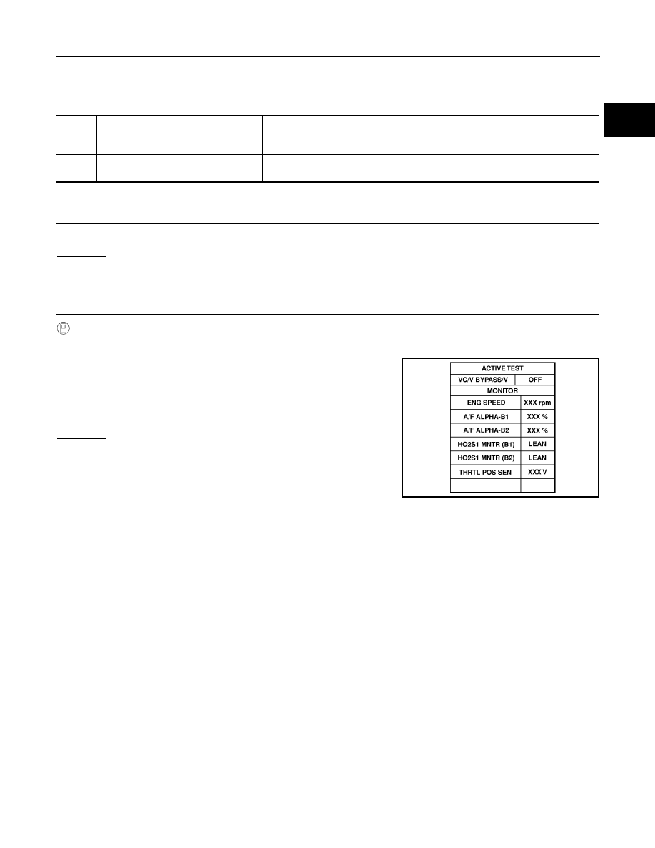
CHECK VACUUM CUT VALVE BYPASS VALVE CIRCUIT

 With CONSULT-II

1.

Turn ignition switch OFF and then ON.

2.

Select  “VC/V BYPASS/V” in “ACTIVE TEST” mode with CON-
SULT-II.

3.

Touch “ON/OFF” on CONSULT-II screen.

4.

Make sure that clicking sound is heard from the vacuum cut
valve bypass valve.

OK or NG

OK

>>  GO TO 7.

NG

>> GO TO 3.

TER-

MINAL 

NO.

WIRE 

COLOR

ITEM

CONDITION

DATA (DC Voltage)

120

P/B

Vacuum cut valve bypass 
valve

[Ignition switch: ON]

BATTERY VOLTAGE
(11 - 14V)

SEF014Z

EC-1684

[VG33ER]

DTC P1490 VACUUM CUT VALVE BYPASS VALVE

3. 

CHECK VACUUM CUT VALVE BYPASS VALUE POWER SUPPLY CIRCUIT

 Without CONSULT-II

1.

Turn ignition switch OFF.

2.

Disconnect vacuum cut valve bypass valve harness connector.

3.

Turn ignition switch ON.

4.

Check voltage between terminal 1 and ground with CONSULT-II
or tester.

OK or NG

OK >> GO 

TO 

5.

NG

>> GO TO 4.

4. 

DETECT MALFUNCTIONING PART

Check the following.

Harness connectors E43, M65

Harness connectors M67, C1

Fuse block (J/B) connector E49

10A fuse 

Harness for open or short between vacuum cut valve bypass valve and fuse

>> Repair harness or connectors.

5. 

CHECK VACUUM CUT VALVE BYPASS VALVE OUTPUT SIGNAL CIRCUIT FOR OPEN AND SHORT

1.

Turn ignition switch OFF.

2.

Disconnect ECM harness connector.

3.

Check harness continuity between ECM terminal 120 and vacuum cut valve bypass valve terminal 2.
Refer to Wiring Diagram.

4.

Also check harness for short to ground and short to power.

OK or NG

OK

>> GO TO 7.

NG

>>  GO TO 6.

SEF186S

Voltage: Battery voltage

SEF659W

Continuity should exist.

DTC P1490 VACUUM CUT VALVE BYPASS VALVE

EC-1685

[VG33ER]

C

D

E

F

G

H

I

J

K

L

M

A

EC

6. 

DETECT MALFUNCTIONING PART

Check the following.

Harness connectors C1, M67

Harness connectors M81, F36

Harness for open or short between vacuum cut valve bypass valve and ECM

>> Repair open circuit or short to ground or short to power in harness or connectors.

7. 

CHECK VACUUM CUT VALVE BYPASS VALVE

 With CONSULT-II

1.

Perform “VC/V BYPASS/V” in “ACTIVE TEST” mode.

2.

Check air passage continuity and operation delay time under the
following conditions.

Operation takes less than 1 second.

 Without CONSULT-II

Check air passage continuity and operation delay time under the fol-
lowing conditions.

Operation takes less than 1 second.

OK or NG

OK

>> GO TO 8.

NG

>> Replace vacuum cut valve bypass valve.

8. 

CHECK INTERMITTENT INCIDENT

Refer to 

EC-1297, "TROUBLE DIAGNOSIS FOR INTERMITTENT INCIDENT"

 .

>> INSPECTION END.

SEF014Z

Condition

VC/V BYPASS/V

Air passage continuity between A and B

ON

Yes

OFF

No

PBIB1429E

Condition

Air passage continuity between A and B

12V direct current supply 
between terminals 1 and 2

Yes

No supply

No

PBIB1430E

EC-1686

[VG33ER]

DTC P1491 VACUUM CUT VALVE BYPASS VALVE

DTC P1491 VACUUM CUT VALVE BYPASS VALVE

PFP:17372

Description

UBS00E1Z

COMPONENT DESCRIPTION

The vacuum cut valve and vacuum cut valve bypass valve are
installed in parallel on the EVAP purge line between the fuel tank and
the EVAP canister.
The vacuum cut valve prevents the intake manifold vacuum from
being applied to the fuel tank.
The vacuum cut valve bypass valve is a solenoid type valve and
generally remains closed. It opens only for on board diagnosis.
The vacuum cut valve bypass valve responds to signals from the
ECM. When the ECM sends an ON (ground) signal, the valve is
opened. The vacuum cut valve is then bypassed to apply intake
manifold vacuum to the fuel tank.

EVAPORATIVE EMISSION SYSTEM DIAGRAM

CONSULT-II Reference Value in Data Monitor Mode

UBS00E20

Specification data are reference values.

SEF186S

PBIB1438E

MONITOR ITEM

CONDITION

SPECIFICATION

VC/V BYPASS/V

Ignition switch: ON

OFF


Content   ..  643  644  645  646   ..