Nissan Frontier D22. Manual - part 636


  Index      Nissan     Nissan Frontier D22 Pickup (1998-2004 year) - Service and Repair Manual


Search            


Content   ..  634  635  636  637   ..


Nissan Frontier D22. Manual - part 636


DTC P1444 EVAP CANISTER PURGE VOLUME CONTROL SOLENOID VALVE

EC-1647

[VG33ER]

C

D

E

F

G

H

I

J

K

L

M

A

EC

Specification data are reference values and are measured between each terminal and ground.

CAUTION:

Do not use ECM ground terminals when measuring input/output voltage. Doing so may result in dam-
age to the ECM's transistor. Use a ground other than the ECM terminals, such as the ground.

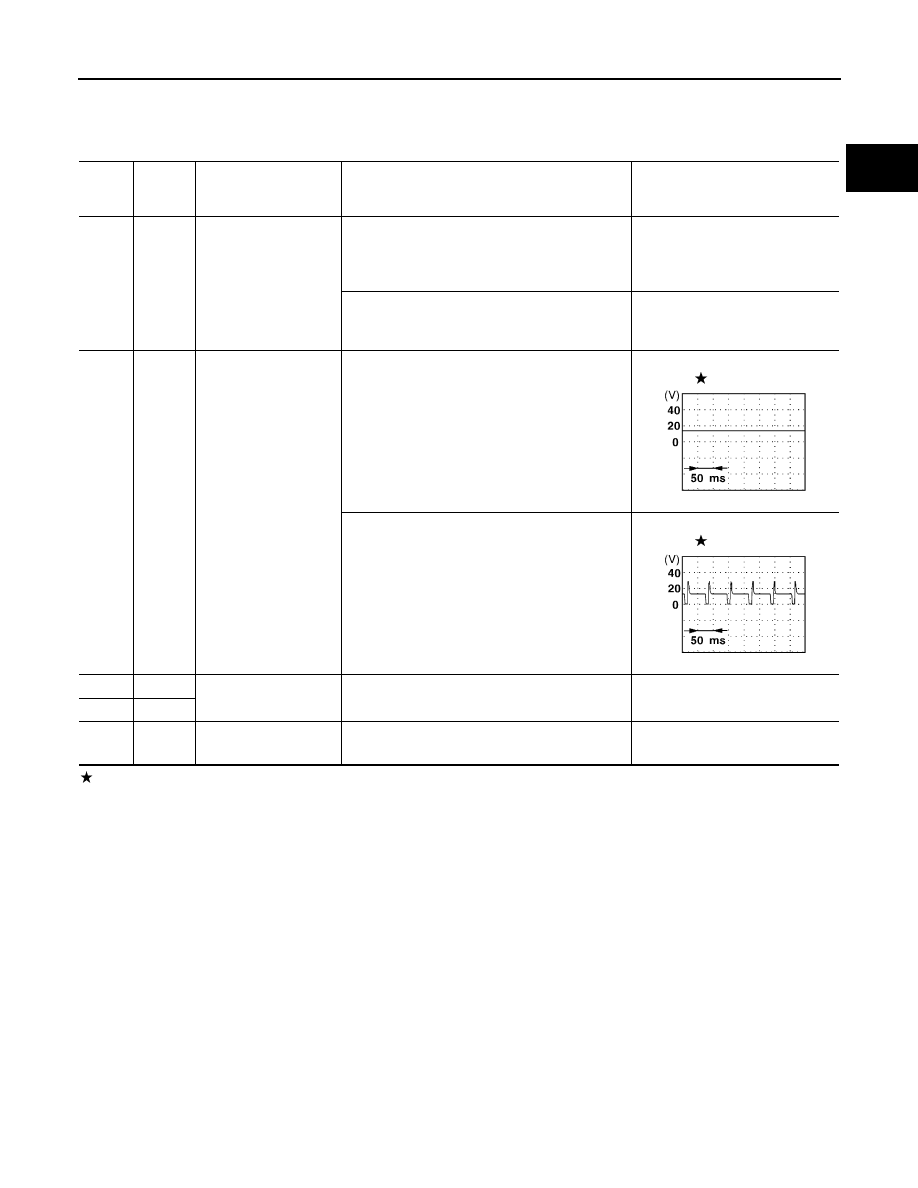
: Average voltage for pulse signal (Actual pulse signal can be confirmed by oscilloscope.)

TER-

MINAL 

NO.

WIRE 

COLOR

ITEM

CONDITION

DATA (DC Voltage)

4

OR/B

ECM relay (Self shut-
off)

[Engine is running]
[Ignition switch: OFF]

For a few seconds after turning ignition switch 
OFF

0 - 1.5V

[Ignition switch: OFF]

A few seconds passed after turning ignition 
switch OFF

BATTERY VOLTAGE
(11 - 14V)

5

R/Y

EVAP canister purge 
volume control solenoid 
valve

[Engine is running]

Idle speed

BATTERY VOLTAGE

(11 - 14V)

[Engine is running]

Engine speed is 2,000 rpm
(More than 100 seconds after starting engine)

BATTERY VOLTAGE

(11 - 14V)

67

B/P

Power supply for ECM

[Ignition switch: ON]

BATTERY VOLTAGE
(11 - 14V)

72

B/P

117

B/P

Current return

[Engine is running]

Idle speed

BATTERY VOLTAGE
(11 - 14V)

SEF994U

SEF995U

EC-1648

[VG33ER]

DTC P1444 EVAP CANISTER PURGE VOLUME CONTROL SOLENOID VALVE

Diagnostic Procedure

UBS00E15

1. 

CHECK EVAP CANISTER PURGE VOLUME CONTROL SOLENOID VALVE POWER SUPPLY CIR-

CUIT

1.

Turn ignition switch OFF.

2.

Disconnect EVAP canister purge volume control solenoid valve
harness connector.

3.

Turn ignition switch ON.

4.

Check voltage between terminal 1 and engine ground with CON-
SULT-II or tester.

OK or NG

OK

>> GO TO 3.

NG

>> GO TO 2.

2. 

DETECT MALFUNCTIONING PART

Check the following.

Harness connectors F36, M81

Harness connectors M65, E43

Harness for open or short between EVAP canister purge volume control solenoid valve and ECM relay

Harness for open or short between EVAP canister purge volume control solenoid valve and ECM

>> Repair harness or connectors.

3. 

CHECK EVAP CANISTER PURGE VOLUME CONTROL SOLENOID VALVE OUTPUT SIGNAL CIR-

CUIT FOR OPEN AND SHORT

1.

Turn ignition switch OFF.

2.

Disconnect ECM harness connector.

3.

Check harness continuity between ECM terminal 5 and EVAP canister purge volume control solenoid
valve terminal 2. Refer to Wiring Diagram.

4.

Also check harness for short to ground and short to power.

OK or NG

OK

>> GO TO 5.

NG

>> GO TO 4.

AEC652A

Voltage: Battery voltage

SEF646W

Continuity should exist.

DTC P1444 EVAP CANISTER PURGE VOLUME CONTROL SOLENOID VALVE

EC-1649

[VG33ER]

C

D

E

F

G

H

I

J

K

L

M

A

EC

4. 

DETECT MALFUNCTIONING PART

Check the following.

Harness connectors E43, M65

Harness connectors M81, F36

Harness for open or short between EVAP canister purge volume control solenoid valve and ECM

>> Repair open circuit or short to ground or short to power in harness or connectors.

5. 

CHECK EVAP CONTROL SYSTEM PRESSURE SENSOR HOSE

Check disconnection or improper connection of hose connected to EVAP control system pressure sensor.

OK or NG

OK

>> GO TO 6.

NG

>> Repair it.

6. 

CHECK EVAP CONTROL SYSTEM PRESSURE SENSOR CONNECTOR

1.

Disconnect EVAP control system pressure sensor harness con-
nector.

2.

Check connectors for water.
Water should not exist.

OK or NG

OK

>> GO TO 7. 

NG

>> Replace EVAP control system pressure sensor.

7. 

CHECK EVAP CONTROL SYSTEM PRESSURE SENSOR

1.

Remove EVAP control system pressure sensor with its harness connector connected.

2.

Remove hose from EVAP control system pressure sensor.

3.

Turn ignition switch ON.

4.

Use pump to apply vacuum and pressure to EVAP control system pressure sensor as shown in figure.

5.

Check input voltage between ECM terminal 62 and ground.

CAUTION:

Always calibrate the vacuum pump gauge when using it.

Do not apply below 

93.3 kPa (700 mmHg, 27.56 inHg) or

over 101.3 kPa (760 mmHg, 29.92 inHg) of pressure.

OK or NG

OK (with CONSULT-II)>>GO TO 8.
OK (without CONSULT-II)>>GO TO 9.
NG

>> Replace EVAP control system pressure sensor.

AEC651A

Applied vacuum

Voltage V

Not applied

1.4 - 4.8

-26.7 kpa (-200 mmHg, -7.87 inHg)

2.1 to 2.5V lower than above value

PBIB1426E

EC-1650

[VG33ER]

DTC P1444 EVAP CANISTER PURGE VOLUME CONTROL SOLENOID VALVE

8. 

CHECK EVAP CANISTER PURGE VOLUME CONTROL SOLENOID VALVE

 With CONSULT-II

1.

Start engine.

2.

Perform  “PURG VOL CONT/V” in “ACTIVE TEST” mode with
CONSULT-II. Check that engine speed varies according to the
valve opening.
If OK, inspection end. If NG, go to following step.

3.

Check air passage continuity.

If NG, replace the EVAP canister purge volume control solenoid
valve.
OK or NG

OK

>> GO TO 10.

NG

>> Replace EVAP canister purge volume control solenoid

valve.

9. 

CHECK EVAP CANISTER PURGE VOLUME CONTROL SOLENOID VALVE

 Without CONSULT-II

Check air passage continuity.

If NG, replace the EVAP canister purge volume control solenoid
valve.

OK or NG

OK

>> GO TO 10.

NG

>> Replace EVAP canister purge volume control solenoid

valve.

SEF985Y

Condition

PURG VOL CONT/V value

Air passage continuity 

between A and B

100%

 Yes

0%

No

SEF660U

Condition

Air passage continuity 

between A and B

12V direct current supply between 
terminals 1 and 2

Yes

No supply

No

SEF661U


Content   ..  634  635  636  637   ..