Nissan Frontier D22. Manual - part 617


  Index      Nissan     Nissan Frontier D22 Pickup (1998-2004 year) - Service and Repair Manual


Search            


Content   ..  615  616  617  618   ..


Nissan Frontier D22. Manual - part 617


DTC P0500 VSS

EC-1571

[VG33ER]

C

D

E

F

G

H

I

J

K

L

M

A

EC

Specification data are reference values and are measured between each terminal and ground.

CAUTION:

Do not use ECM ground terminals when measuring input/output voltage. Doing so may result in dam-
age to the ECM's transistor. Use a ground other than the ECM terminals, such as the ground.

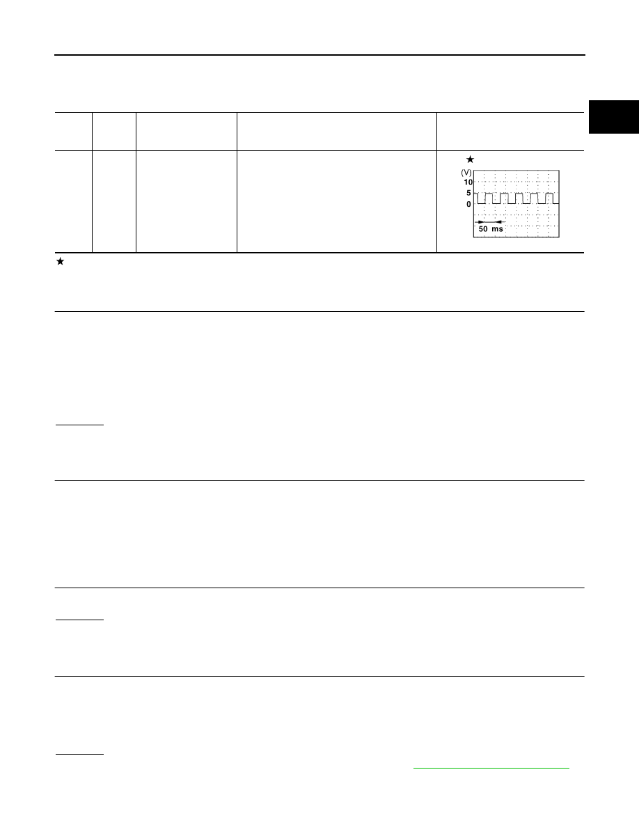
: Average voltage for pulse signal (Actual pulse signal can be confirmed by oscilloscope.)

Diagnostic Procedure

UBS00DZ2

1. 

CHECK VEHICLE SPEED SENSOR INPUT SIGNAL CIRCUIT FOR OPEN AND SHORT

1.

Turn ignition switch OFF.

2.

Disconnect ECM harness connector and combination meter harness connector.

3.

Check harness continuity between ECM terminal 29 and combination meter terminal 2. 
Refer to Wiring Diagram.

4.

Also check harness for short to ground and short to power.

OK or NG

OK

>> GO TO 3.

NG

>> GO TO 2.

2. 

DETECT MALFUNCTIONING PART

Check the following.

Harness connectors M81, F36

Harness for open or short between ECM and combination meter

>> Repair open circuit or short to ground or short to power in harness or connectors.

3. 

CHECK SPEEDOMETER FUNCTION

Make sure that speedometer functions properly.

OK or NG

OK

>> GO TO 5.

NG

>> GO TO 4.

4. 

CHECK SPEEDOMETER CIRCUIT FOR OPEN AND SHORT

Check the following.

Harness connectors M59, F27

Harness connectors F43, F201

Harness for open or short between combination meter and vehicle speed sensor

OK or NG

OK

>> Check combination meter and vehicle speed sensor. Refer to 

DI-3, "METERS AND GAUGES"

 .

NG

>> Repair open circuit or short to ground or short to power in harness or connectors.

TER-

MINAL 

NO.

WIRE 

COLOR

ITEM

CONDITION

DATA (DC Voltage)

29

G/B

Vehicle speed sensor

[Engine is running]

Lift up the vehicle.

Shift lever: 2nd (M/T), D (A/T)

Vehicle speed is 40 km/h (25 MPH)

2 - 3V

SEF996U

Continuity should exist.

EC-1572

[VG33ER]

DTC P0500 VSS

5. 

CHECK INTERMITTENT INCIDENT

Refer to 

EC-1297, "TROUBLE DIAGNOSIS FOR INTERMITTENT INCIDENT"

 .

>> INSPECTION END.

DTC P0505 ISC SYSTEM

EC-1573

[VG33ER]

C

D

E

F

G

H

I

J

K

L

M

A

EC

DTC P0505 ISC SYSTEM

PFP:23781

Description

UBS00DZ3

SYSTEM DESCRIPTION

This system automatically controls engine idle speed to a specified level. Idle speed is controlled through fine
adjustment of the amount of air which bypasses the throttle valve via IACV-AAC valve. The IACV-AAC valve
repeats ON/OFF operation according to the signal sent from the ECM. The camshaft position sensor detects
the actual engine speed and sends a signal to the ECM. The ECM then controls the ON/OFF time of the IACV-
AAC valve so that engine speed coincides with the target value memorized in ECM. The target engine speed
is the lowest speed at which the engine can operate steadily. The optimum value stored in the ECM is deter-
mined by taking into consideration various engine conditions, such as during warm up, deceleration, and
engine load (air conditioner and power steering).

COMPONENT DESCRIPTION
IACV-AAC Valve

The IACV-AAC valve is moved by ON/OFF pulses from the ECM.
The longer the ON pulse, the greater the amount of air that will flow
through the valve. The more air that flows through the valve, the
higher the idle speed.

CONSULT-II Reference Value in Data Monitor Mode

UBS00DZ4

Specification data are reference values.

Sensor

Input Signal to ECM

ECM func-

tion

Actuator

Camshaft position sensor

Engine speed

Idle air 
control

IACV-AAC valve

Mass air flow sensor

Amount of intake air

Engine coolant temperature sensor

Engine coolant temperature

Ignition switch

Start signal

Throttle position sensor

Throttle position

Park/neutral position (PNP) switch

Park/neutral position

Air conditioner switch

Air conditioner operation

Power steering oil pressure switch

Power steering load signal

Battery

Battery voltage

Vehicle speed sensor

Vehicle speed

Ambient air temperature switch

Ambient air temperature

Intake air temperature sensor

Intake air temperature

SEF040E

MONITOR ITEM

CONDITION

SPECIFICATION

IACV-AAC/V

Engine: After warming up

Air conditioner switch: OFF

Shift lever: N (A/T), Neutral (M/T)

No load

Idle

10 - 20%

2,000 rpm

EC-1574

[VG33ER]

DTC P0505 ISC SYSTEM

On Board Diagnosis Logic

UBS00DZ5

DTC Confirmation Procedure

UBS00DZ6

NOTE:

If DTC Confirmation Procedure has been previously conducted, always turn ignition switch OFF and wait
at least 5 seconds before conducting the next test.

Perform PROCEDURE FOR MALFUNCTION A first. If 1st trip DTC cannot confirmed, perform PRO-
CEDURE FOR MALFUNCTION B AND C.

PROCEDURE FOR MALFUNCTION A

TESTING CONDITION:
Before performing the following procedure, confirm that battery voltage is more than 10.5V with igni-
tion switch ON.

 With CONSULT-II

1.

Turn ignition switch ON.

2.

Select “DATA MONITOR” mode with CONSULT-II.

3.

Wait at least 2 seconds.

4.

If 1st trip DTC is detected, go to

EC-1577, "Diagnostic Proce-

dure"

 .

 With GST

Follow the procedure “With CONSULT-II”.

PROCEDURE FOR MALFUNCTION B AND C

TESTING CONDITION:
Before performing the following procedure, confirm that battery voltage is more than 11V at idle.

 With CONSULT-II

1.

Start engine and warm it up to normal operating temperature.

2.

Turn ignition switch OFF and wait at least 5 seconds.

DTC No.

Trouble diagnosis name

DTC detecting condition

Possible cause

P0505

A)

Idle speed control sys-
tem circuit

The IACV-AAC valve does not operate 
properly

Harness or connectors
(The IACV-AAC valve circuit is open)

IACV-AAC valve

B)

Idle speed control sys-
tem RPM lower than 
expected

The IACV-AAC valve does not operate 
properly

Harness or connectors
(The IACV-AAC valve circuit is open)

IACV-AAC valve

C)

Idle speed control sys-
tem RPM higher than 
expected

The IACV-AAC valve does not operate 
properly

Harness or connectors
(The IACV-AAC valve circuit is open)

IACV-AAC valve

SEF174Y


Content   ..  615  616  617  618   ..