Nissan Frontier D22. Manual - part 598
DTC P0441 EVAP CONTROL SYSTEM
EC-1495
[VG33ER]
C
D
E
F
G
H
I
J
K
L
M
A
EC
6.
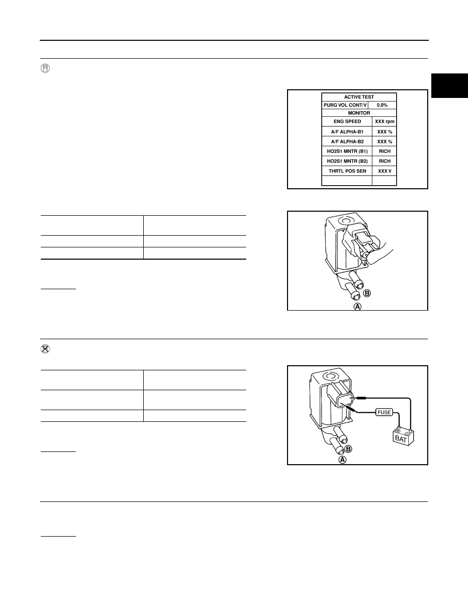
CHECK EVAP CANISTER PURGE VOLUME CONTROL SOLENOID VALVE
With CONSULT-II
1.
Start engine.
2.
Perform “PURG VOL CONT/V” in “ACTIVE TEST” mode with
CONSULT-II. Check that engine speed varies according to the
valve opening.
If OK, inspection end. If NG, go to following step.
3.
Check air passage continuity.
If NG, replace the EVAP canister purge volume control solenoid
valve.
OK or NG
OK
>> GO TO 8.
NG
>> Replace EVAP canister purge volume control solenoid
valve.
7.
CHECK EVAP CANISTER PURGE VOLUME CONTROL SOLENOID VALVE
Without CONSULT-II
Check air passage continuity.
If NG, replace the EVAP canister purge volume control solenoid
valve.
OK or NG
OK
>> GO TO 8.
NG
>> Replace EVAP canister purge volume control solenoid
valve.
8.
CHECK EVAP CONTROL SYSTEM PRESSURE SENSOR HOSE
1.
Turn ignition switch OFF.
2.
Check disconnection or improper connection of hose connected to EVAP control system pressure sensor.
OK or NG
OK
>> GO TO 9.
NG
>> Repair it.
SEF985Y
Condition
PURG VOL CONT/V value
Air passage continuity between A
and B
100%
Yes
0%
No
SEF660U
Condition
Air passage continuity between A
and B
12V direct current supply
between terminals 1 and 2
Yes
No supply
No
SEF661U