Nissan Frontier D22. Manual - part 590


  Index      Nissan     Nissan Frontier D22 Pickup (1998-2004 year) - Service and Repair Manual


Search            


Content   ..  588  589  590  591   ..


Nissan Frontier D22. Manual - part 590


DTC P0300 - P0306 MULTIPLE CYLINDER MISFIRE, NO. 1 - 6 CYLINDER MIS-

FIRE

EC-1463

[VG33ER]

C

D

E

F

G

H

I

J

K

L

M

A

EC

5. 

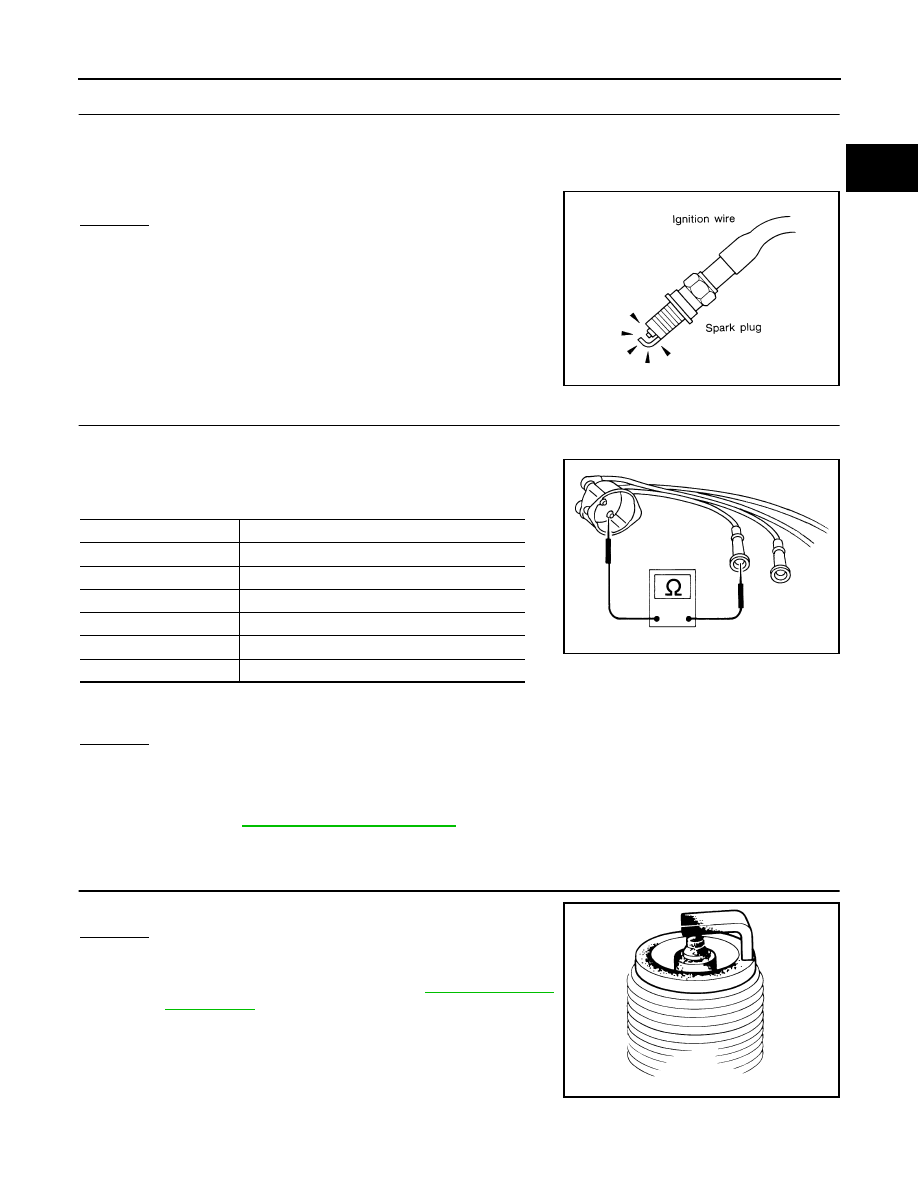
CHECK IGNITION SPARK

1.

Disconnect ignition wire from spark plug.

2.

Connect a known good spark plug to the ignition wire.

3.

Place end of spark plug against a suitable ground and crank engine.

4.

Check for spark.

OK or NG

OK

>> GO TO 7.

NG

>> GO TO 6.

6. 

CHECK IGNITION WIRES

1.

Inspect wires for cracks, damage, burned terminals and for improper fit.

2.

Measure the resistance of wires to their distributor cap terminal.
Move each wire while testing to check for intermittent breaks.
Resistance:

If the resistance exceeds the above specification, inspect ignition wire to distributor cap connection. Clean
connection or replace the ignition wire with a new one.

OK or NG

OK

>> Check the following:

Distributor rotor head for incorrect parts

Ignition coil, power transistor and their circuits
Refer to 

EC-1710, "IGNITION SIGNAL"

 .

NG

>> Replace.

7. 

CHECK SPARK PLUGS

Remove the spark plugs and check for fouling, etc.

OK or NG

OK

>> GO TO 8.

NG

>> Repair or replace spark plug(s) with standard type

one(s). For spark plug type, refer to 

MA-32, "Changing

Spark Plugs"

 .

SEF282G

Cylinder No.

Resistance k

Ω [at 25°C (77°F)]

1

Approx. 6.5

2

Approx. 10.0

3

Approx. 8.5

4

Approx. 12.5

5

Approx. 8.5

6

Approx. 11.0

SEF174P

SEF156I

EC-1464

[VG33ER]

DTC P0300 - P0306 MULTIPLE CYLINDER MISFIRE, NO. 1 - 6 CYLINDER MIS-

FIRE

8. 

CHECK COMPRESSION PRESSURE

Refer to 

EM-102, "Measurement of Compression"

 .

Check compression pressure.

OK or NG

OK

>> GO TO 9.

NG

>> Check pistons, piston rings, valves, valve seats and cylinder head gaskets.

9. 

CHECK FUEL PRESSURE

1.

Install any parts removed.

2.

Release fuel pressure to zero.
Refer to 

EC-1218, "FUEL PRESSURE RELEASE"

 .

3.

Install fuel pressure gauge and check fuel pressure. Refer to 

EC-1218, "FUEL PRESSURE CHECK"

 .

OK or NG

OK

>> GO TO 11.

NG

>> GO TO 10.

10. 

DETECT MALFUNCTIONING PART

Check the following.

Fuel pump and circuit (Refer to 

EC-1725

 .)

Fuel pressure regulator (Refer to 

EC-1219

 .)

Fuel lines (Refer to 

MA-28

 .)

Fuel filter for clogging

>> Repair or replace.

11. 

CHECK IGNITION TIMING

Check the following items. Refer to 

EC-1247, "Basic Inspection"

 .

OK or NG

OK (With CONSULT-II)>>GO TO 12.
OK (Without CONSULT-II)>>GO TO 13.
NG

>> Adjust ignition timing.

Standard

: 1,196 kPa (12.2 kg/cm

2

 , 173 psi)/300 rpm

Minimum

: 883 kPa (9.0 kg/cm

2

 , 128 psi)/300 rpm

Difference between 
each cylinder

: 98 kPa (1.0 kg/cm

2

 , 14 psi)/300 rpm

At idle: Approx. 235 kPa (2.4 kg/cm

2

 , 34 psi)

Items

Specifications

Ignition timing

10

° ± 5° BTDC

Base idle speed

700 

± 50 rpm (in P or N position)

Closed throttle position switch idle 
position adjustment

Feeler gauge thickness and switch 
condition
0.3 mm (0.012 in): ON
0.4 mm (0.016 in): OFF

Target idle speed

750 

± 50 rpm (in P or N position)

DTC P0300 - P0306 MULTIPLE CYLINDER MISFIRE, NO. 1 - 6 CYLINDER MIS-

FIRE

EC-1465

[VG33ER]

C

D

E

F

G

H

I

J

K

L

M

A

EC

12. 

CHECK HEATED OXYGEN SENSOR 1

 With CONSULT-II

1.

Start engine and warm it up to normal operating temperature. 

2.

Select “MANU TRIG” and “HI SPEED” in “DATA MONITOR” mode with CONSULT-II, and select “HO2S1
(B1)/(B2)” and “HO2S1 MNTR (B1)/(B2)”.

3.

 Hold engine speed at 2,000 rpm under no load during the following steps.

4.

Touch “RECORD” on CONSULT-II screen.

5.

Check the following.

“HO2S1 MNTR (B1)/(B2)” in “DATA MONITOR” mode changes
from “RICH” to “LEAN” to “RICH” more than 5 times in 10 sec-
onds.
5 times (cycles) are counted as shown left:

“HO2S1 (B1)/(B2)” voltage goes above 0.6V at least once.

“HO2S1 (B1)/(B2)” voltage goes below 0.3V at least once.

“HO2S1 (B1)/(B2)” voltage never exceeds 1.0V.

CAUTION:

Discard any heated oxygen sensor which has been dropped from a height of more than 0.5 m (19.7
in) onto a hard surface such as a concrete floor; use a new one.

Before installing new oxygen sensor, clean exhaust system threads using Oxygen Sensor Thread
Cleaner tool J-43897-18 or J-43897-12 and approved anti-seize lubricant.

OK or NG

OK

>> GO TO 14.

NG

>> Replace malfunctioning heated oxygen sensor 1.

SEF967Y

SEF647Y

SEF648Y

EC-1466

[VG33ER]

DTC P0300 - P0306 MULTIPLE CYLINDER MISFIRE, NO. 1 - 6 CYLINDER MIS-

FIRE

13. 

CHECK HEATED OXYGEN SENSOR 1 (BANK1)(BANK2)

 Without CONSULT-II

1.

Start engine and warm it up to normal operating temperature.

2.

Set voltmeter probes between ECM terminal 50 (bank1 sensor
signal) or 51 (bank2 sensor signal) and engine ground.

3.

Check the following with engine speed held at 2,000 rpm con-
stant under no load.

The voltage fluctuates between 0 to 0.3V and 0.6 to 1.0V more
than 5 times within 10 seconds.

The maximum voltage is over 0.6V at least 1 time.

The minimum voltage is below 0.3V at least 1 time.

The voltage never exceeds 1.0V.

1 time: 0 - 0.3V 

→ 0.6 - 1.0V → 0 - 0.3V

2 times: 0 - 0.3V 

→ 0.6 - 1.0V → 0 - 0.3V → 0.6 - 1.0V → 0 - 0.3V

CAUTION:

Discard any heated oxygen sensor which has been dropped from a height of more than 0.5 m (19.7
in) onto a hard surface such as a concrete floor; use a new one.

Before installing new oxygen sensor, clean exhaust system threads using Oxygen Sensor Thread
Cleaner tool J-43897-18 or J-43897-12 and approved anti-seize lubricant.

OK or NG

OK

>> GO TO 14.

NG

>> Replace malfunctioning heated oxygen sensor 1.

14. 

CHECK MASS AIR FLOW SENSOR

 With CONSULT-II

Check mass air flow sensor signal in “DATA MONITOR” mode with CONSULT-II.

 With GST

Check mass air flow sensor signal in MODE 1 with GST.

OK or NG

OK

>> GO TO 15.

NG

>> Check connectors for rusted terminals or loose connections in the mass air flow sensor circuit or

engine grounds. Refer to 

EC-1327

 .

15. 

CHECK SYMPTOM MATRIX CHART

Check items on the rough idle symptom in 

EC-1260, "Symptom Matrix Chart"

 .

OK or NG

OK

>> GO TO 16.

NG

>> Repair or replace. 

16. 

ERASE THE 1ST TRIP DTC

Some tests may cause a 1st trip DTC to be set.
Erase the 1st trip DTC from the ECM memory after performing the tests. Refer to 

EC-1233, "HOW TO ERASE

EMISSION-RELATED DIAGNOSTIC INFORMATION"

 .

>> GO TO 17.

PBIB2157E

3.3 - 4.8 g·m/sec

: at idling

12.0 - 14.9 g·m/sec

: at 2,500 rpm

3.3 - 4.8 g·m/sec

: at idling

12.0 - 14.9 g·m/sec

: at 2,500 rpm


Content   ..  588  589  590  591   ..