Nissan Frontier D22. Manual - part 575


  Index      Nissan     Nissan Frontier D22 Pickup (1998-2004 year) - Service and Repair Manual


Search            


Content   ..  573  574  575  576   ..


Nissan Frontier D22. Manual - part 575


DTC P0134, P0154 HO2S1

EC-1403

[VG33ER]

C

D

E

F

G

H

I

J

K

L

M

A

EC

Specification data are reference values and are measured between each terminal and ground.

CAUTION:

Do not use ECM ground terminals when measuring input/output voltage. Doing so may result in dam-
age to the ECM's transistor. Use a ground other than the ECM terminals, such as the ground.

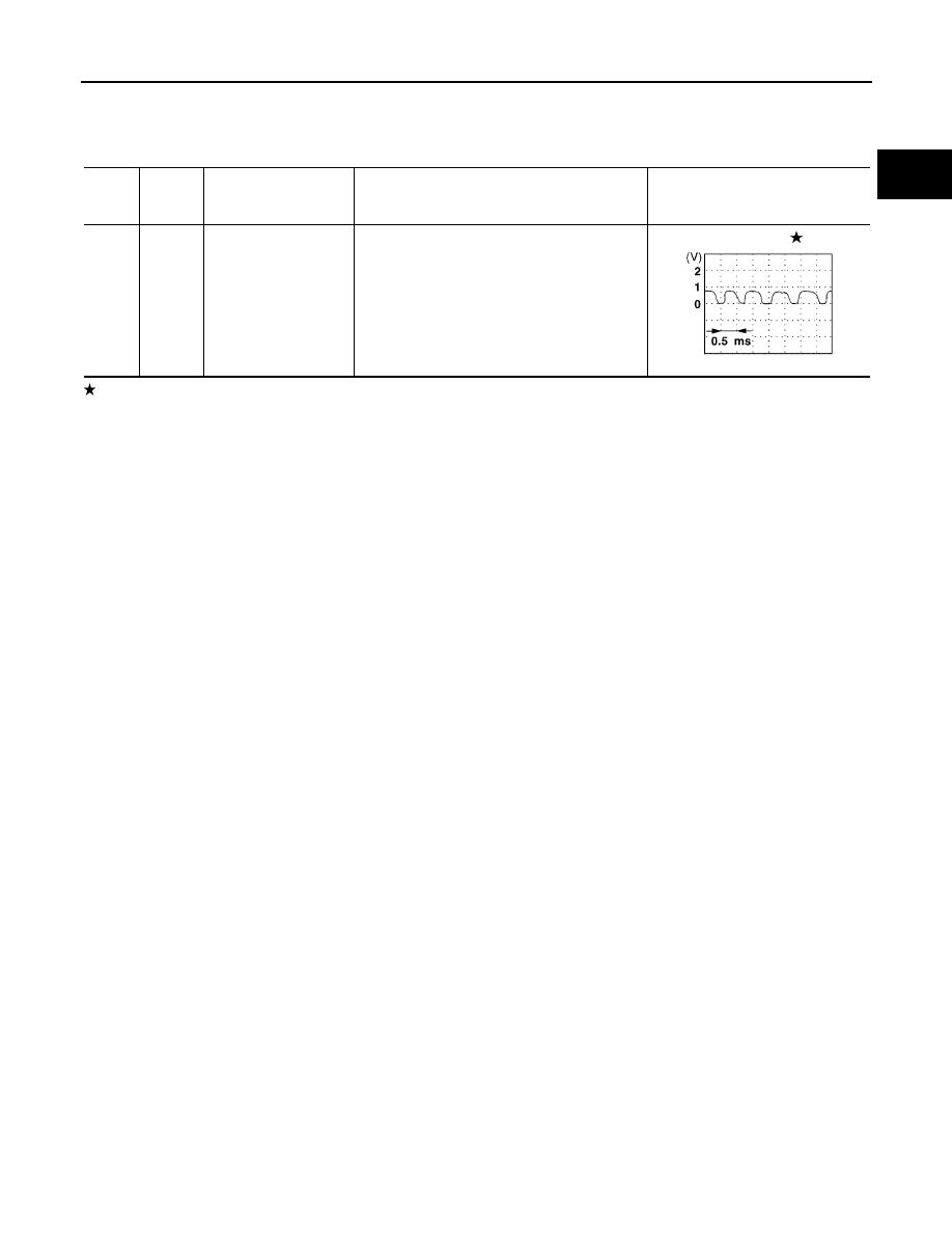
: Average voltage for pulse signal (Actual pulse signal can be confirmed by oscilloscope.

TER-

MINAL 

NO.

WIRE 

COLOR

ITEM

CONDITION

DATA (DC Voltage)

51

G

Heated oxygen sensor 
1 (bank 2)

[Engine is running]

Warm-up condition

Engine speed is 2,000 rpm

0 - Approximately 1.0V

SEF002V

EC-1404

[VG33ER]

DTC P0134, P0154 HO2S1

Diagnostic Procedure

UBS00DVI

1. 

INSPECTION START

1.

Turn ignition switch OFF.

2.

Loosen and retighten engine ground screws.

3.

Make sure HO2S 1 harness protector color, and disconnect cor-
responding heated oxygen sensor 1  harness connector.

>> GO TO 2.

BBIA0418E

PBIB0636E

BBIA0189E

DTC P0134, P0154 HO2S1

EC-1405

[VG33ER]

C

D

E

F

G

H

I

J

K

L

M

A

EC

2. 

CHECK HO2S 1 INPUT SIGNAL CIRCUIT FOR OPEN AND SHORT

1.

Disconnect ECM harness connector.

2.

Check harness continuity between ECM terminal and HO2S1 terminal as follows.
Refer to Wiring Diagram.

3.

Check harness continuity between ECM terminal or HO2S1 terminal and ground as follows.
Refer to Wiring Diagram.

4.

Also check harness for short to power.

OK or NG

OK (With CONSULT-II)>>GO TO 3.
OK (Without CONSULT-II)>> GO TO 4.
NG

>> Repair open circuit or short to ground or short to power in harness or connectors.

DTC

Terminals

Bank

ECM

Sensor

P0134

50

2

Bank 1 

P0154

51

2

Bank 2

Continuity should exist.

DTC

Terminals

Bank

ECM or sensor

Ground

P0134

50 or 2

Ground

Bank 1 

P0154

51 or 2

Ground

Bank 2

Continuity should not exist.

EC-1406

[VG33ER]

DTC P0134, P0154 HO2S1

3. 

CHECK HEATED OXYGEN SENSOR 1

 With CONSULT-II

1.

Start engine and warm it up to normal operating temperature.

2.

Select  “MANU TRIG” in “DATA MONITOR” mode with CON-
SULT-II, and select “HO2S1 (B1)/(B2)” and “HO2S1 MNTR (B1)/
(B2)”.

3.

Hold engine speed at 2,000 rpm under no load during the follow-
ing steps.

4.

Touch “RECORD” on CONSULT-II screen.

5.

Check the following.

“HO2S1 MNTR (B1)/(B2)” in “DATA MONITOR” mode changes
from “RICH” to “LEAN” to “RICH” more than 5 times in 10 sec-
onds.
5 times (cycles) are counted as shown below.

“HO2S1 (B1)/(B2)” voltage goes above 0.6V at least once.

“HO2S1 (B1)/(B2)” voltage goes below 0.3V at least once.

“HO2S1 (B1)/(B2)” voltage never exceeds 1.0V.

CAUTION:

Discard any heated oxygen sensor which has been dropped from a height of more than 0.5 m (19.7
in) onto a hard surface such as a concrete floor; use a new one.

Before installing new oxygen sensor, clean exhaust system threads using Oxygen Sensor Thread
Cleaner tool J-43897-18 or J-43897-12 and approved anti-seize lubricant.

OK or NG

OK

>> GO TO 5.

NG

>> Replace malfunctioning heated oxygen sensor 1.

SEF967Y

SEF647Y

SEF648Y


Content   ..  573  574  575  576   ..