Index Nissan Nissan Frontier D22 Pickup (1998-2004 year) - Service and Repair Manual
Search
Content .. 567 568 569 570 ..
Nissan Frontier D22. Manual - part 569
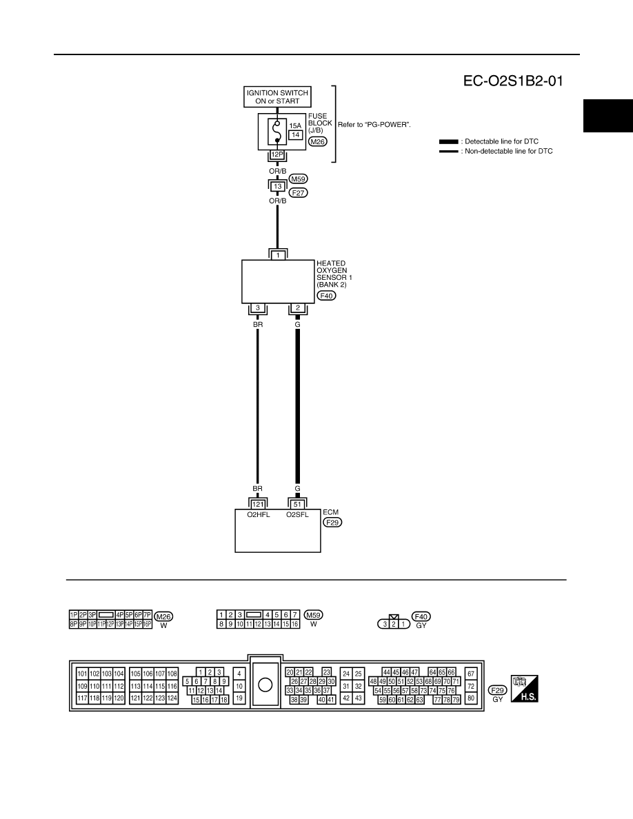
DTC P0132, P0152 HO2S1
EC-1379
[VG33ER]
C
D
E
F
G
H
I
J
K
L
M
A
EC
BANK 2
BBWA1076E