Nissan Frontier D22. Manual - part 562


  Index      Nissan     Nissan Frontier D22 Pickup (1998-2004 year) - Service and Repair Manual


Search            


Content   ..  560  561  562  563   ..


Nissan Frontier D22. Manual - part 562


DTC P0121 TP SENSOR

EC-1351

[VG33ER]

C

D

E

F

G

H

I

J

K

L

M

A

EC

On Board Diagnosis Logic

UBS00DU5

DTC Confirmation Procedure

UBS00DU6

NOTE:

Perform PROCEDURE FOR MALFUNCTION A first. If the 1st trip DTC cannot be confirmed, per-
form PROCEDURE FOR MALFUNCTION B.

If DTC Confirmation Procedure has been previously conducted, always turn ignition switch OFF and wait
at least 5 seconds before conducting the next test.

PROCEDURE FOR MALFUNCTION A

 With CONSULT-II

1.

Turn ignition switch ON.

2.

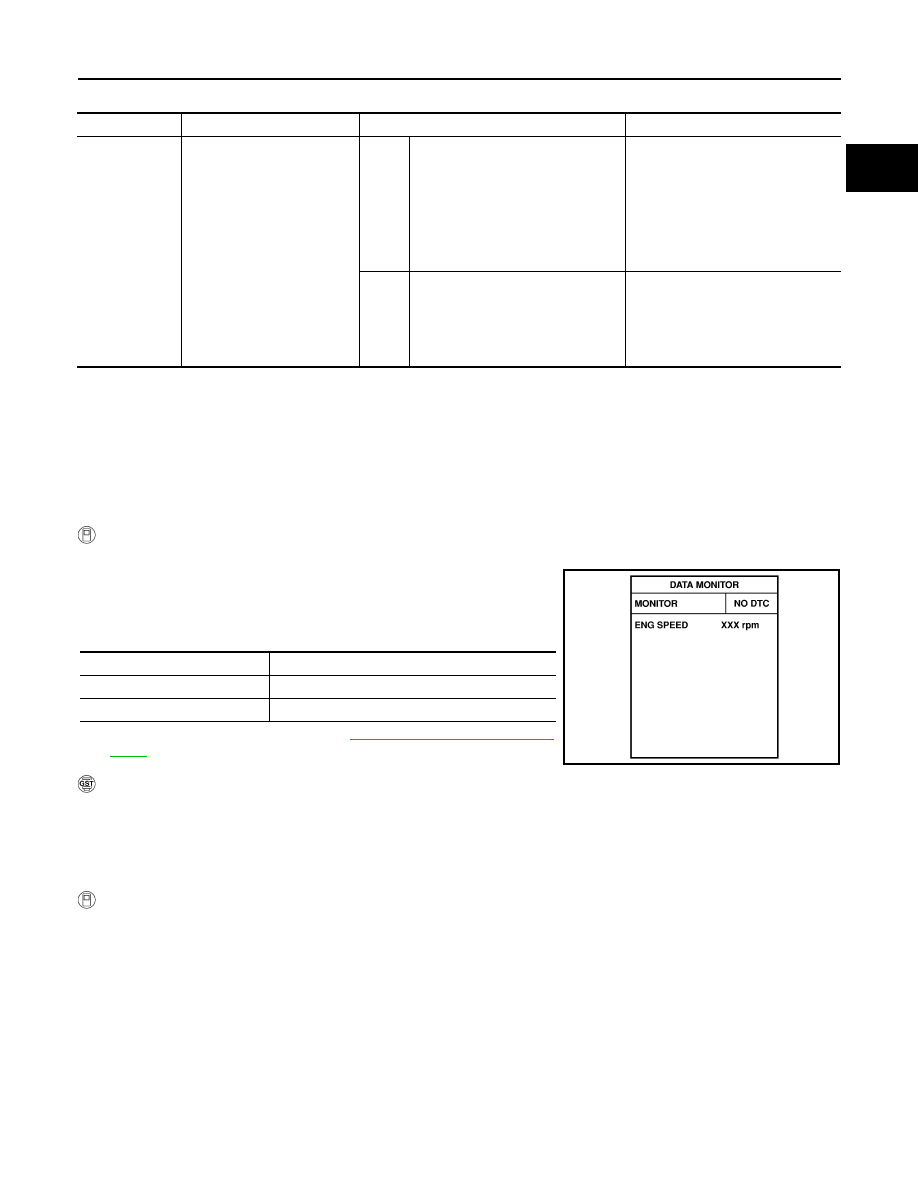
Select “DATA MONITOR” mode with CONSULT-II.

3.

Start engine and let it idle for at least 10 seconds.
If idle speed is over 1,000 rpm, maintain the following conditions
for at least 10 seconds to keep engine speed below 1,000 rpm.

4.

If 1st trip DTC is detected, go to 

EC-1354, "Diagnostic Proce-

dure"

 .

 With GST

Follow the procedure “With CONSULT-II”.

PROCEDURE FOR MALFUNCTION B

CAUTION:

Always drive vehicle at a safe speed.

 With CONSULT-II

1.

Start engine and warm it up to normal operating temperature.

2.

Turn ignition switch OFF and wait at least 5 seconds.

3.

Turn ignition switch ON.

DTC No.

Trouble diagnosis name

DTC detecting condition

Possible cause

P0121

Throttle position sensor cir-
cuit range/performance prob-
lem

A)

A high voltage from the sensor is 
sent to ECM under light load driving 
condition.

Harness or connectors
(The TP sensor circuit is open or 
shorted.)

TP sensor

Fuel injector

Camshaft position sensor

Mass air flow sensor

B)

A low voltage from the sensor is 
sent to ECM under heavy load driv-
ing condition.

Harness or connectors
(The TP sensor circuit is open or 
shorted.)

Intake air leaks

TP sensor

Selector lever

Suitable position except P or N

Brake pedal

Depressed

Vehicle speed

0 km/h (0 MPH)

SEF058Y

EC-1352

[VG33ER]

DTC P0121 TP SENSOR

4.

Select  “MANU TRIG” in “DATA MONITOR” mode with CON-
SULT-II.

5.

Select “THRTL POS SEN” and “ABSOL TH·P/S” in “DATA MON-
ITOR” mode with CONSULT-II.

6.

Press RECORD on CONSULT-II screen at the same time accel-
erator pedal is depressed.

7.

Print out the recorded graph and check the following:

The voltage rise is linear in response to accelerator pedal
depression.

The voltage when accelerator pedal is fully depressed is approx-
imately 4V.
If NG, go to 

EC-1354, "Diagnostic Procedure"

 .

If OK, go to following step.

8.

Select  “AUTO TRIG” in “DATA MONITOR” mode with CON-
SULT-II.

9.

Maintain the following conditions for at least 10 consecutive sec-
onds.

10. If 1st trip DTC is detected, go to 

EC-1354, "Diagnostic Procedure"

 . 

 With GST

Follow the procedure “With CONSULT-II”.

CMPS·RPM (REF)

More than 2,000 rpm

MAS AIR/FL SE

More than 3V

COOLAN TEMP/S

More than 70

°C (158°F)

IACV-AAC/V

Less than 80%

Selector lever

Suitable position

Driving location

Driving vehicle uphill (Increased engine load) will 
help maintain the driving conditions required for 
this test.

SEF177Y

SEF174Z

SEF805Z

DTC P0121 TP SENSOR

EC-1353

[VG33ER]

C

D

E

F

G

H

I

J

K

L

M

A

EC

Wiring Diagram

UBS00DU7

BBWA0473E

EC-1354

[VG33ER]

DTC P0121 TP SENSOR

Specification data are reference values and are measured between each terminal and ground.

CAUTION:

Do not use ECM ground terminals when measuring input/output voltage. Doing so may result in dam-
age to the ECM's transistor. Use a ground other than the ECM terminals, such as the ground.

Diagnostic Procedure

UBS00DU8

1. 

INSPECTION START

Which malfunction (A or B) is duplicated?

A or B

A

>> GO TO 4.

B

>> GO TO 2.

2. 

ADJUST THROTTLE POSITION SENSOR

Check the following items. Refer to 

EC-1247, "Basic Inspection"

>> GO TO 3. 

3. 

CHECK INTAKE SYSTEM.

1.

Turn ignition switch OFF.

2.

Check the following for connection.

Air duct

Vacuum hoses

Intake air passage between air duct to intake manifold collector

OK or NG

OK

>> GO TO 4.

NG

>> Reconnect the parts.

TER-

MINAL 

NO.

WIRE 

COLOR

ITEM

CONDITION

DATA (DC Voltage)

23

L

Throttle position sensor

[Engine is running]

Warm-up condition

More than -40.0 kpa (-300 mmHg, -11.81 inHg) 
of vacuum is applied to the throttle opener with 
a hand vacuum pump

Accelerator pedal is fully released

0.15 - 0.85V

[Ignition switch: ON]

Engine stopped

Accelerator pedal is fully depressed

3.5 - 4.7V

42

B/W

Sensor power supply

[Ignition switch: ON]

Approximately 5V

43

BR

Sensor ground

[Engine is running]

Warm-up condition

Idle speed

Approximately 0V

Items

Specifications

Ignitions timing

10

° ± 5° BTDC

Base idle speed

700 

± 50 rpm (in P or N position)

Closed throttle position switch idle 
position adjustment

Feeler gauge thickness and switch 
condition
0.3 mm (0.012 in): ON
0.4 mm (0.016 in): OFF

Target idle speed

750 

± 50 rpm (in P or N position)


Content   ..  560  561  562  563   ..