Nissan Frontier D22. Manual - part 543
TROUBLE DIAGNOSIS
EC-1275
[VG33ER]
C
D
E
F
G
H
I
J
K
L
M
A
EC
101
OR/L
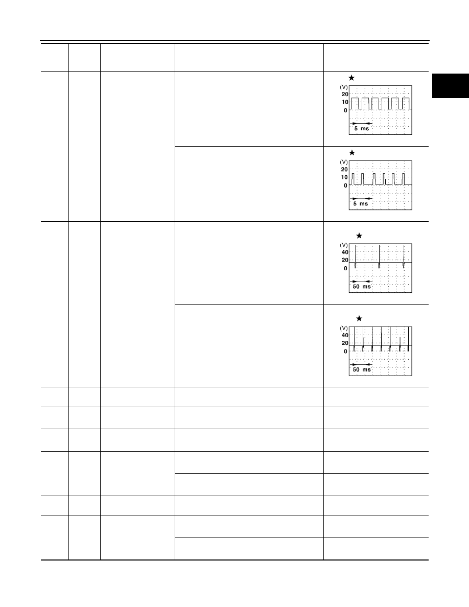
IACV-AAC valve
[Engine is running]
●
Warm-up condition
●
Idle speed
NOTE:
The pulse cycle changes depending on rpm at
idle
8 - 11V
[Engine is running]
●
Warm-up condition
●
Engine speed is 3,000 rpm
7 - 10V
102
104
106
109
111
113
W/B
W/R
W/G
W/L
W/PU
W
Injector No. 1
Injector No. 3
Injector No. 5
Injector No. 2
Injector No. 4
Injector No. 6
[Engine is running]
●
Warm-up condition
●
Idle speed
NOTE:
The pulse cycle changes depending on rpm at
idle
BATTERY VOLTAGE
(11 - 14V)
[Engine is running]
●
Warm-up condition
●
Engine speed is 2,000 rpm
BATTERY VOLTAGE
(11 - 14V)
108
R/G
EVAP canister vent
control valve
[Ignition switch: ON]
BATTERY VOLTAGE
(11 - 14V)
116
B/R
ECM ground
[Engine is running]
●
Idle speed
Engine ground
117
B/P
Current return
[Engine is running]
●
Idle speed
BATTERY VOLTAGE
(11 - 14V)
119
BR/Y
Heated oxygen sensor
1 heater (bank 1)
[Engine is running]
●
Engine speed is below 2,800 rpm
Approximately 0.4V
[Engine is running]
●
Engine speed is above 2,800 rpm
BATTERY VOLTAGE
(11 - 14V)
120
P/B
Vacuum cut valve
bypass valve
[Ignition switch: ON]
BATTERY VOLTAGE
(11 - 14V)
121
BR
Heated oxygen sensor
1 heater (bank 2)
[Engine is running]
●
Engine speed is below 2,800 rpm
Approximately 0.4V
[Engine is running]
●
Engine speed is above 2,800 rpm
BATTERY VOLTAGE
(11 - 14V)
TER-
MINAL
NO.
WIRE
COLOR
ITEM
CONDITION
DATA (DC Voltage)
SEF005V
SEF692W
SEF007V
SEF008V