Nissan Frontier D22. Manual - part 532


  Index      Nissan     Nissan Frontier D22 Pickup (1998-2004 year) - Service and Repair Manual


Search            


Content   ..  530  531  532  533   ..


Nissan Frontier D22. Manual - part 532


ON BOARD DIAGNOSTIC (OBD) SYSTEM

EC-1231

[VG33ER]

C

D

E

F

G

H

I

J

K

L

M

A

EC

The time required for each diagnosis varies with road surface conditions, weather, altitude, individual driv-
ing habits, etc.
Zone A refers to the range where the time required, for the diagnosis under normal conditions*, is the
shortest.
Zone B refers to the range where the diagnosis can still be performed if the diagnosis is not completed
within zone A.

*: Normal conditions refer to the following:

Sea level

Flat road

Ambient air temperature: 20 - 30

°C (68 - 86°F)

Diagnosis is performed as quickly as possible under normal conditions.
Under different conditions [For example: ambient air temperature other than 20 - 30

°C (68 - 86°F)], diag-

nosis may also be performed.

Pattern 1:

The engine is started at the engine coolant temperature of 

10 to 35°C (14 to 95°F)

(where the voltage between the ECM terminal 59 and ground is 3.0 - 4.3V).

The engine must be operated at idle speed until the engine coolant temperature is greater than
70

°C (158°F) (where the voltage between the ECM terminal 59 and ground is lower than 1.4V).

The engine is started at the tank fuel temperature of warmer than 0

°C (32°F) (where the voltage

between the ECM terminal 60 and ground is less than 4.1V).

Pattern 2:

When steady-state driving is performed again even after it is interrupted, each diagnosis can be con-
ducted. In this case, the time required for diagnosis may be extended.

Pattern 3:

The driving pattern outlined in *2 must be repeated at least 3 times.

Pattern 4:

Tests are performed after the engine has been operated for at least 17 minutes.

The accelerator pedal must be held very steady during steady-state driving.

If the accelerator pedal is moved, the test must be conducted all over again.

*1: Depress the accelerator pedal until vehicle speed is 90 km/h (56 MPH), then release the accelerator pedal
and keep it released for more than 10 seconds. Depress the accelerator pedal until vehicle speed is 90 km/h
(56 MPH) again.
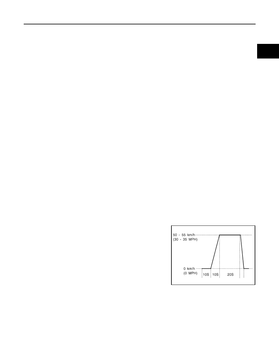
*2: Operate the vehicle in the following driving pattern.

1.

Decelerate vehicle to 0 km/h (0 MPH) and let engine idle.

2.

Repeat driving pattern shown below at least 10 times.

During acceleration, hold the accelerator pedal as steady as
possible. 

*3: Checking the vehicle speed with CONSULT-II or GST is advised.

Suggested Transmission Gear Position for A/T Models
Set the selector lever in the D position with the overdrive switch turned ON.
Suggested upshift speeds for M/T models
Shown below are suggested vehicle speeds for shifting into a higher gear. These suggestions relate to fuel
economy and vehicle performance. Actual upshift speeds will vary according to road conditions, the weather
and individual driving habits.

SEF414S

EC-1232

[VG33ER]

ON BOARD DIAGNOSTIC (OBD) SYSTEM

Suggested Maximum Speed in Each Gear
Downshift to a lower gear if the engine is not running smoothly, or if you need to accelerate.
Do not exceed the maximum suggested speed (shown below) in any gear. For level road driving, use the high-
est gear suggested for that speed. Always observe posted speed limits and drive according to the road condi-
tions to ensure safe operation. Do not over-rev the engine when shifting to a lower gear as it may cause
engine damage or loss of vehicle control.

TEST VALUE AND TEST LIMIT (GST ONLY — NOT APPLICABLE TO CONSULT-II)

The following is the information specified in Mode 6 of SAE J1979.
The test value is a parameter used to determine whether a system/circuit diagnostic test is “OK” or “NG” while
being monitored by the ECM during self-diagnosis. The test limit is a reference value which is specified as the
maximum or minimum value and is compared with the test value being monitored.
These data (test value and test limit) are specified by Test ID (TID) and Component ID (CID) and can be dis-
played on the GST screen.

For normal acceleration in low altitude areas 

[less than 1,219 m (4,000 ft)]:

For quick acceleration in low altitude areas 
and high altitude areas [over 1,219 m (4,000 
ft)]:

Gear change

ACCEL shift point km/h (MPH)

km/h (MPH)

1st to 2nd

24 (15)

24 (15)

2nd to 3rd

40 (25)

40 (25)

3rd to 4th

64 (40)

64 (40)

4th to 5th

72 (45)

72 (45)

Gear

km/h (MPH)
2WD (AUTO mode)

1st

50 (30)

2nd

95 (60)

Item

Self-diagnostic test item

DTC

Test value (GST display)

Test limit

Conversion

TID

CID

CATALYST

Three way catalyst function (Bank 1)

P0420

01H

01H

Max.

1/128

P0420

02H

81H

Min.

1

Three way catalyst function (Bank 2)

P0430

03H

02H

Max.

1/128

P0430

04H

82H

Min.

1

EVAP SYSTEM

EVAP control system (Small leak)

P0442

 05H

03H

Max.

1/128mm

2

 EVAP control system purge flow monitoring

P0441

06H

83H

Min.

20mV

EVAP control system (Very small leak)

P0456

07H

03H

Max.

1/128mm

2

P1456

07H

03H

Max.

1/128mm

2

ON BOARD DIAGNOSTIC (OBD) SYSTEM

EC-1233

[VG33ER]

C

D

E

F

G

H

I

J

K

L

M

A

EC

HOW TO ERASE EMISSION-RELATED DIAGNOSTIC INFORMATION
How to Erase DTC

 With CONSULT-II

NOTE:
If the DTC is not for A/T related items (see 

EC-1185

 ), skip steps 2 through 4.

1.

If the ignition switch stays ON after repair work, be sure to turn ignition switch OFF once. Wait at least 5
seconds and then turn it ON (engine stopped) again.

2.

Turn CONSULT-II “ON” and touch “A/T”.

3.

Touch “SELF-DIAG RESULTS”.

4.

Touch “ERASE”. [The DTC in the TCM (Transmission control module) will be erased.] Then touch “BACK”
twice.

5.

Touch “ENGINE”.

6.

Touch “SELF-DIAG RESULTS”.

7.

Touch “ERASE”. (The DTC in the ECM will be erased.)

HO2S

Heated oxygen sensor 1 (bank 1)

P0133

09H

04H

Max.

16ms

P1143

0AH

84H

Min.

10mV

P1144

0BH

04H

Max.

10mV

P0132

0CH

04H

Max.

10mV

P0134

0DH

04H

Max.

1s

Heated oxygen sensor 1 (bank 2)

P0153

11H

05H

Max.

16ms

P1163

12H

85H

Min.

10mV

P1164

13H

05H

Max.

10mV

P0152

14H

05H Max.

10mV

P0154

15H

05H

Max.

1s

Heated oxygen sensor 2 (bank 1)

P0139

19H

86H

Min.

10mV/500ms

P1147

1AH

86H

Min.

10mV

P1146

1BH

 06H

Max.

10mV

P0138

1CH

06H

Max.

10mV

Heated oxygen sensor 2 (bank 2)

P0159

21H

87H

Min.

10mV/500ms

P1167

22H

87H

Min.

10mV

P1166

23H

07H

Max.

10mV

P0158

24H

07H

Max.

10mV

HO2S HEATER

Heated oxygen sensor 1 (bank 1)

P0032

29H

08H

Max.

20mV

P0031

2AH

88H

Min.

20mV

Heated oxygen sensor 1 (bank 2)

P0052

2BH

09H

Max.

20mV

P0051

2CH

89H

Min.

20mV

Heated oxygen sensor 2 (bank 1)

P0038

2DH

0AH

Max.

20mV

P0037

2EH

8AH

Min.

20mV

Heated oxygen sensor 2 (bank 2)

P0058

2FH

0BH

Max.

20mV

P0057

30H

8BH

Min.

20mV

Item

Self-diagnostic test item

DTC

Test value (GST display)

Test limit

Conversion

TID

CID

EC-1234

[VG33ER]

ON BOARD DIAGNOSTIC (OBD) SYSTEM

If DTCs are displayed for both ECM and TCM (Transmission control module), they need to be erased indi-
vidually from the ECM and TCM (Transmission control module).

The emission related diagnostic information in the ECM can be erased by selecting “ERASE” in the “SELF-
DIAG RESULTS” mode with CONSULT-II.

 With GST

The emission related diagnostic information in the ECM can be erased by selecting Mode 4 with GST.

NOTE:
If the DTC is not for A/T related items (see 

EC-1185

 ), skip step 2.

1.

If the ignition switch stays ON after repair work, be sure to turn ignition switch OFF once. Wait at least 5
seconds and then turn it ON (engine stopped) again.

2.

Perfor

AT-188

 . (The DTC in TCM will be erased.)

3.

Select MODE 4 with GST (Generic Scan Tool).

If the battery is disconnected, the emission-related diagnostic information will be lost within 24
hours.

The following data are cleared when the ECM memory is erased.

Diagnostic trouble codes

1st trip diagnostic trouble codes 

Freeze frame data

1st trip freeze frame data

System readiness test (SRT) codes

Test values

 Others

Actual work procedures are explained using a DTC as an example. Be careful so that not only the DTC, but all
of the data listed above, are cleared from the ECM memory during work procedures.

SEF823YD


Content   ..  530  531  532  533   ..