Nissan Frontier D22. Manual - part 511


  Index      Nissan     Nissan Frontier D22 Pickup (1998-2004 year) - Service and Repair Manual


Search            


Content   ..  509  510  511  512   ..


Nissan Frontier D22. Manual - part 511


START SIGNAL

EC-1147

[VG33E]

C

D

E

F

G

H

I

J

K

L

M

A

EC

Specification data are reference values and are measured between each terminal and ground.

CAUTION:

Do not use ECM ground terminals when measuring input/output voltage. Doing so may result in dam-
age to the ECM's transistor. Use a ground other than the ECM terminals, such as the ground.

Diagnostic Procedure

UBS00DQF

1. 

INSPECTION START

Do you have CONSULT-II?

Yes or No

Yes

>> GO TO 2.

No

>> GO TO 3.

2. 

CHECK OVERALL FUNCTION

 With CONSULT-II

1.

Turn ignition switch ON.

2.

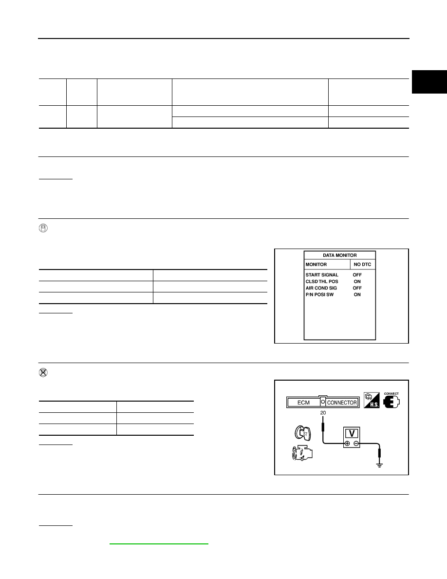
Check “START SIGNAL” in “DATA MONITOR” mode with CON-
SULT-II under the following conditions.

OK or NG

OK

>> INSPECTION END.

NG

>> GO TO 4.

3. 

CHECK OVERALL FUNCTION

 Without CONSULT-II

Check voltage between ECM terminal 20 and ground under the fol-
lowing conditions.

OK or NG

OK

>> INSPECTION END.

NG

>> GO TO 4. 

4. 

CHECK STARTING SYSTEM

Turn ignition switch OFF, then turn it to START.
Does starter motor operate?

Yes or No

Yes

>> GO TO 5.

No

>> Refer to 

SC-9, "STARTING SYSTEM"

 .

TER-

MINAL 

NO.

WIRE 

COLOR

ITEM

CONDITION

DATA (DC Voltage)

20

L/OR

Start signal

[Ignition switch: ON]

Approximately 0V

[Ignition switch: START]

9 - 12V

Condition

“START SIGNAL”

Ignition switch ON

OFF

Ignition switch START

ON

PBIB0182E

Condition

Voltage

Ignition switch START

Battery voltage

Other positions

Approx. 0V

SEF733U

EC-1148

[VG33E]

START SIGNAL

5. 

CHECK FUSE

1.

Turn ignition switch OFF.

2.

Disconnect 7.5A fuse.

3.

Check if 7.5A fuse is OK.

OK or NG

OK

>> GO TO 6.

NG

>> Replace 7.5A fuse.

6. 

CHECK START SIGNAL INPUT SIGNAL CIRCUIT FOR OPEN AND SHORT

1.

Disconnect ECM harness connector.

2.

Check harness continuity between ECM terminal 20 and fuse block. Refer to Wiring Diagram.

3.

Also check harness for short to ground and short to power.

OK or NG

OK

>> GO TO 8.

NG

>> GO TO 7.

7. 

DETECT MALFUNCTIONING PART

Check the following.

Harness connectors M81, F36

Harness for open or short between ECM and fuse

>> Repair open circuit or short to ground or short to power in harness or connectors.

8. 

CHECK INTERMITTENT INCIDENT

Refer to 

EC-696, "TROUBLE DIAGNOSIS FOR INTERMITTENT INCIDENT"

 .

>> INSPECTION END.

Continuity should exist.

FUEL PUMP CIRCUIT

EC-1149

[VG33E]

C

D

E

F

G

H

I

J

K

L

M

A

EC

FUEL PUMP CIRCUIT

PFP:17042

Description

UBS00DQG

SYSTEM DESCRIPTION

The ECM activates the fuel pump for several seconds after the ignition switch is turned ON to improve engine
startability. If the ECM receives a 120

° signal from the camshaft position sensor, it knows that the engine is

rotating, and causes the pump to operate. If the 120

° signal is not received when the ignition switch is ON, the

engine stalls. The ECM stops pump operation and prevents battery discharging, thereby improving safety. The
ECM does not directly drive the fuel pump. It controls the ON/OFF fuel pump relay, which in turn controls the
fuel pump.

COMPONENT DESCRIPTION

The fuel pump with a fuel damper is an in-tank type (the pump and
damper are located in the fuel tank).

CONSULT-II Reference Value in Data Monitor Mode

UBS00DQH

Specification data are reference values.

Sensor

Input Signal to ECM

ECM function

Actuator

Camshaft position sensor

Engine speed

Fuel pump control

Fuel pump relay

Ignition switch

Start signal

Condition

Fuel pump operation

Ignition switch is turned to ON.

Operates for 5 seconds

Engine running and cranking

Operates

When engine is stopped

Stops in 1.5 seconds 

Except as shown above

Stops

SEF018S

MONITOR ITEM

CONDITION

SPECIFICATION

FUEL PUMP RLY

Ignition switch is turned to ON. (Operates for 5 seconds.)

Engine running or cranking

ON

Except as shown above

OFF

EC-1150

[VG33E]

FUEL PUMP CIRCUIT

Wiring Diagram

UBS00DQI

BBWA1098E


Content   ..  509  510  511  512   ..