Nissan Frontier D22. Manual - part 484


  Index      Nissan     Nissan Frontier D22 Pickup (1998-2004 year) - Service and Repair Manual


Search            


Content   ..  482  483  484  485   ..


Nissan Frontier D22. Manual - part 484


DTC P1147, P1167 HO2S2

EC-1039

[VG33E]

C

D

E

F

G

H

I

J

K

L

M

A

EC

5. 

CHECK HO2S2  INPUT SIGNAL CIRCUIT FOR OPEN AND SHORT

1.

Turn ignition switch “OFF”.

2.

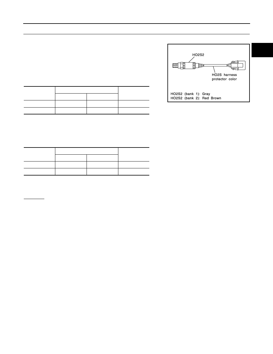
Check heated oxygen sensor 2 harness protector color.

3.

Disconnect corresponding heated oxygen sensor 2 harness
connector.

4.

Disconnect ECM harness connector.

5.

Check harness continuity between ECM terminal and HO2S2
terminal as follows.
Refer to Wiring Diagram.

6.

Check harness continuity between ECM terminal or HO2S2 terminal and ground as follows.

Refer to Wiring Diagram.

7.

Also check harness for short to power.

OK or NG

OK (With CONSULT-II)>>GO TO 6.
OK (Without CONSULT-II)>>GO TO 7.
NG

>> Repair open circuit or short to ground or short to power in harness or connectors.

DTC

Terminals

Bank

ECM

Sensor

P1147

56

1

Bank 1 

P1167

57

1

Bank 2

Continuity should exist.

PBIB1423E

DTC

Terminals

Bank

ECM or sensor

Ground

P1147

56 or 1

Ground

Bank 1 

P1167

57 or 1

Ground

Bank 2

Continuity should not exist.

EC-1040

[VG33E]

DTC P1147, P1167 HO2S2

6. 

CHECK HEATED OXYGEN SENSOR 2

 With CONSULT-II

1.

Turn ignition switch ON and select “DATA MONITOR” mode with CONSULT-II.

2.

Start engine and warm it up to the normal operating temperate.

3.

Turn ignition switch OFF and wait at least 10 seconds.

4.

Start engine and keep the engine speed between 3,500 and 4,000 rpm for at least 1 minute under no load.

5.

Let engine idle for 1 minute.

6.

Select “FUEL INJECTION” in “ACTIVE TEST” mode, and select
“HO2S2 (B1)/(B2)” as the monitor item with CONSULT-II.

7.

Check “HO2S2 (B1)/(B2)” at idle speed when adjusting “FUEL INJECTION” to 

±25%.

“HO2S2 (B1)/(B2)” should be above 0.62V at least once when the “FUEL INJECTION” is +25%.
“HO2S2 (B1)/(B2)” should be below 0.48V at least once when the “FUEL INJECTION” is 

25%.

CAUTION:

Discard any heated oxygen sensor which has been dropped from a height of more than 0.5 m
(19.7 in) onto a hard surface such as a concrete floor; use a new one.

Before installing new oxygen sensor, clean exhaust system threads using Oxygen Sensor
Thread Cleaner tool J-43897-18 or J-43897-12 and approved anti-seize lubricant.

OK or NG

OK

>> GO TO 8.

NG

>> Replace malfunctioning heated oxygen sensor 2.

SEF662Y

SEF989RD

DTC P1147, P1167 HO2S2

EC-1041

[VG33E]

C

D

E

F

G

H

I

J

K

L

M

A

EC

7. 

CHECK HEATED OXYGEN SENSOR 2

 Without CONSULT-II

1.

Start engine warm it up to the normal operating temperature.

2.

Turn ignition switch OFF and wait at least 10 seconds.

3.

Start engine and keep the engine speed between 3,500 and 4,000 rpm for at least 1 minute under no load.

4.

Let engine idle for 1 minute.

5.

Set voltmeter probes between ECM terminal 56 [HO2S2 (B1) signal] or 57 [HO2S2 (B2) signal] and
engine ground.

6.

Check the voltage when revving up to 4,000 rpm under no load
at least 10 times.
(Depress and release accelerator pedal as soon as possible.)
The voltage should be above 0.62V at least once during this
procedure.
If the voltage is above 0.62V at step 6, step 7 is not neces-
sary.

7.

Keep vehicle at idling for 10 minutes, then check voltage. Or
check the voltage when coasting from 80 km/h (50 MPH) in D
position with “OD” OFF (A/T), 3rd gear position (M/T).
The voltage should be below 0.48V at least once during this
procedure.

8.

If NG, replace heated oxygen sensor 2.

CAUTION:

Discard any heated oxygen sensor which has been dropped from a height of more than 0.5 m (19.7
in) onto a hard surface such as a concrete floor; use a new one.

Before installing new oxygen sensor, clean exhaust system threads using Oxygen Sensor Thread
Cleaner tool J-43897-18 or J-43897-12 and approved anti-seize lubricant.

OK or NG

OK

>> GO TO 8.

NG

>> Replace malfunctioning heated oxygen sensor 2.

8. 

CHECK INTERMITTENT INCIDENT

Refer to 

EC-696, "TROUBLE DIAGNOSIS FOR INTERMITTENT INCIDENT"

 .

>> INSPECTION END.

Removal and Installation

UBS00DNS

HEATED OXYGEN SENSOR 2

Refer to 

EX-3, "EXHAUST SYSTEM"

 .

PBIB1437E

EC-1042

[VG33E]

DTC P1148, P1168 CLOSED LOOP CONTROL

DTC P1148, P1168 CLOSED LOOP CONTROL

PFP:22690

On Board Diagnosis Logic

UBS00DNT

These self-diagnoses have the one trip detection logic.

DTC Confirmation Procedure

UBS00DNU

CAUTION:

Always drive vehicle at a safe speed.

NOTE:
If DTC Confirmation Procedure has been previously conducted, always turn ignition switch OFF and wait at
least 5 seconds before conducting the next test.
TESTING CONDITION:

Never raise engine speed above 2,800 rpm during the “DTC Confirmation Procedure”. If the engine
speed limit is exceeded, retry the procedure from step 2.

Before performing the following procedure, confirm that battery voltage is more than 11V at idle.

 WITH CONSULT-II

1.

Start engine and warm it up to normal operating temperature.

2.

Select “DATA MONITOR” mode with CONSULT-II.

3.

Hold engine speed at 2,000 rpm and check one of the following.

“HO2S1 (B1)/(B2)” voltage should go above 0.70V at least once.

“HO2S1 (B1)/(B2)” voltage should go below 0.21V at least once.
If the check result is NG, perform 

EC-1043, "Diagnostic Proce-

dure"

 .

If the check result is OK, perform the following step.

4.

Let engine idle at least 5 minutes.

5.

Maintain the following condition at least 50 consecutive sec-
onds.

During this test, P0134 and/or P0154 may be displayed on CONSULT-II screen.

6.

If DTC is detected, go to 

EC-1043, "Diagnostic Procedure"

 .

Overall Function Check

UBS00DNV

Use this procedure to check the overall function of the closed loop control. During this check, a DTC might not
be confirmed.

 WITH GST

1.

Start engine and warm it up to normal operating temperature.

DTC No.

Trouble diagnosis name

DTC detecting condition

Possible cause

P1148
(Bank 1)

Closed loop control 
function

The closed loop control function for bank 1 
does not operate even when vehicle is driving 
in the specified condition.

The heated oxygen sensor 1 circuit is 
open or shorted.

Heated oxygen sensor 1

Heated oxygen sensor heater

P1168
(Bank 2)

The closed loop control function for bank 2 
does not operate even when vehicle is driving 
in the specified condition.

B/FUEL SCHDL

3.3 msec or more

ENG SPEED

1,600 rpm or more

Selector lever

Suitable position

VHCL SPEED SE

More than 70 km/h (43 MPH)

SEF967Y


Content   ..  482  483  484  485   ..